Tool support for lathes

A tool holder and lathe technology, applied in lathes, turning equipment, turning equipment, etc., can solve the problems of high cost and complex structure, and achieve the effect of low additional time

Inactive Publication Date: 2006-10-04
MICROSWISS TECH
View PDF0 Cites 6 Cited by
  • Summary
  • Abstract
  • Description
  • Claims
  • Application Information

AI Technical Summary

Problems solved by technology

To avoid this, complex and expensive turret heads with different tools are used

Method used


Image

  • Tool support for lathes
  • Tool support for lathes
  • Tool support for lathes

Examples


Embodiment Construction

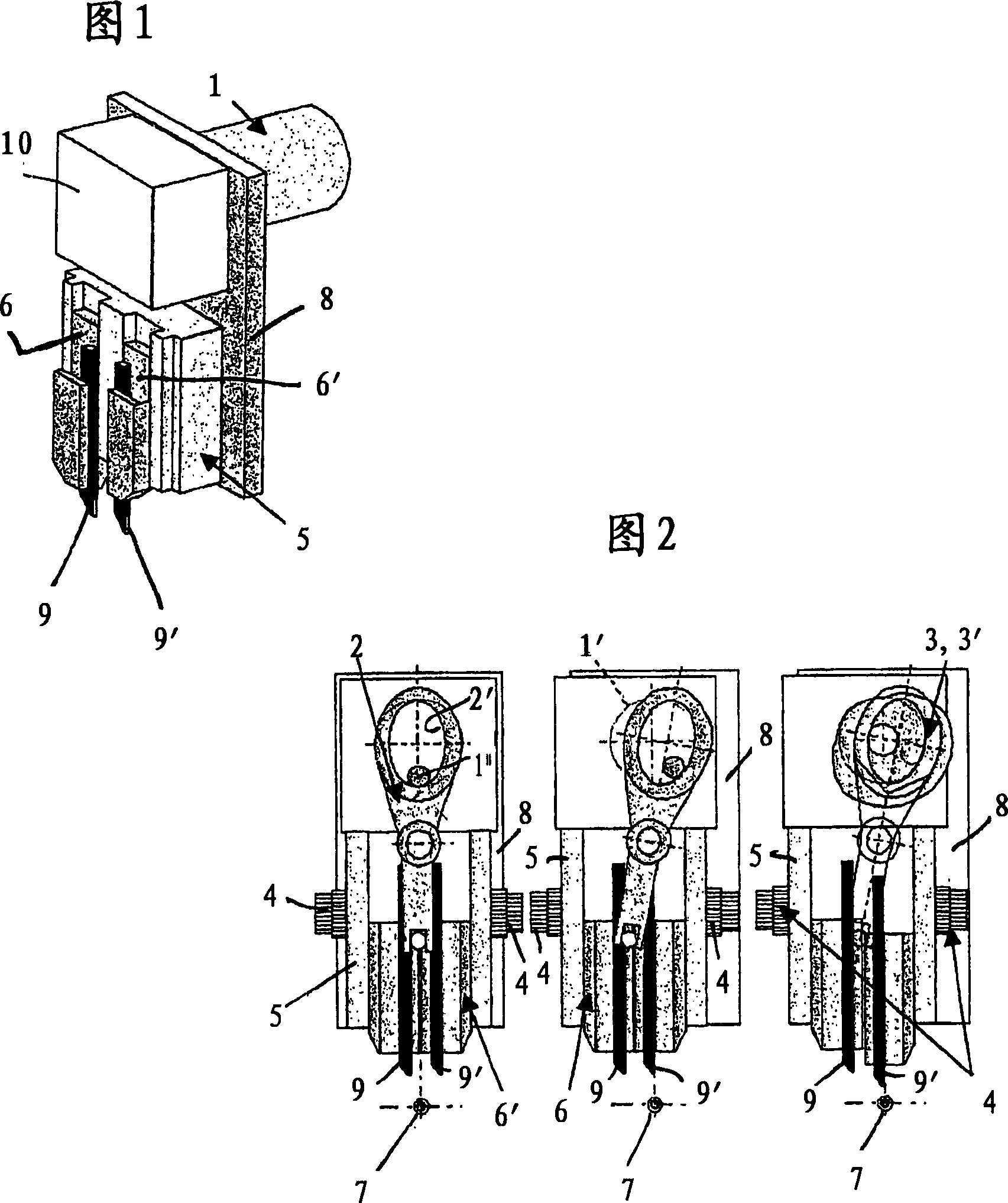
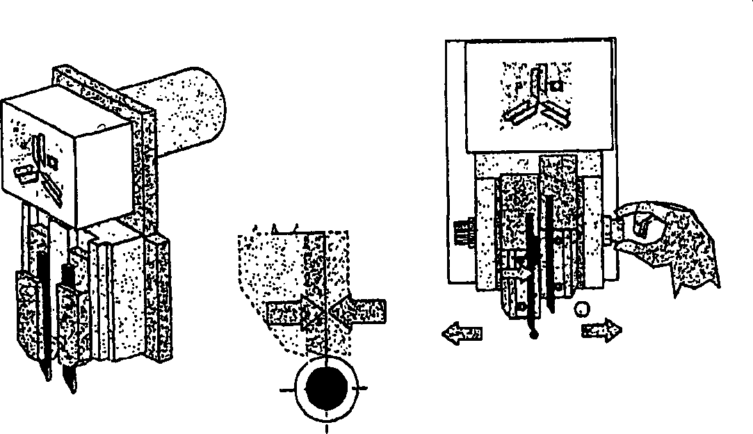
[0018] Figure 1 of the accompanying drawings shows a purely schematic representation of a tool holder according to the invention, which comprises a central drive motor 1 and a base frame 8 on which a transversely movable, with two The slide seat 5 of the knife holder 6, 6'. Different tools 9, 9' are fixed in the tool holders 6, 6'. Behind the movable cover 10 connected to the slide 5 there is the actual drive of the control elements 2 and 3, 3' (see FIG. 2 ).

[0019] The base frame 8 is usually built on a Z-slide (not shown), which allows additional controlled movement in the Z direction (along the main axis).

[0020] By means of the additional Z-movement, a simultaneous machining process can be realized which results in a considerable increase in productivity, especially for longitudinal cutting automatic lathes.

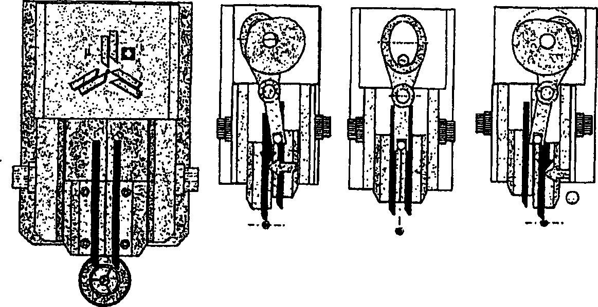
[0021] Figure 2 schematically shows the working principle of a double or twin tool holder:

[0022] The motor 1 drives the control part lever 2 and cam 3 via ...


PUM


Abstract

The tool support comprises a basic structure ( 8 ) on which a slide ( 5 ) is movable in a controlled manner transversely to the spindle axis ( 7 ), two tool holders ( 6 ) being mounted on said slide which are displaceable parallel to each other and serving to hold different tools ( 9,9 '), said holders ( 6,6 ') being selectively displaceable in the direction of the spindle axis ( 7 ) or away from that axis through an angle of 90 DEG with respect to the direction of movement of the slide ( 5 ), and further comprising driving means ( 1,2,3,3' ) to displace the slide ( 5 ) and the tool holders ( 6,6 ') along their axis of movement (Y,Z) into a predetermined working position.

Description

technical field [0001] The invention relates to a tool holder which is arranged on a working spindle of a lathe for cutting workpieces. Background technique [0002] Tool holders for mounting tools on the working spindle of lathes are known and are used for machining workpieces of any material. Depending on the work to be performed, a suitable tool is selected and mounted on the tool holder, which is associated with sometimes time-consuming changeover times (additional times). To avoid this, complex and expensive turret heads with different tools are used. Contents of the invention [0003] The object of the present invention is to realize a tool holder which, while achieving the highest precision, is very simple in construction and in practice reduces the additional time (tool change) to almost zero. [0004] This object is solved according to the invention by the characterizing features of claim 1 in a tool holder of the type defined at the outset. [0005] Particular...

Claims


Application Information

Patent Timeline
Patent Type & Authority Applications(China)
IPC IPC(8): B23Q3/00B23B29/06B23B29/18B23B29/26B23B29/24B23B29/32B23Q1/54
CPCB23B29/323B23Q1/5418Y10T82/2587Y10T82/2543Y10T82/192Y10T82/2508Y10T82/16591Y10T29/5173
Inventor B·E·于贝尔哈特
Owner MICROSWISS TECH
Why Eureka
Try Eureka