
Method for processing panel into protuberant drum wall-thickening part by utilizing stamping process

A technology for sheet metal processing and workpiece, applied in the field of metal parts processing technology, to achieve the effect of improving service life and ensuring strength requirements

Inactive Publication Date: 2006-10-11
夏勤三
View PDF0 Cites 13 Cited by
  • Summary
  • Abstract
  • Description
  • Claims
  • Application Information

AI Technical Summary

Problems solved by technology

[0004] The invention provides a method for processing plates into thickened workpieces with raised cylinder walls by stamping technology, which solves the shortcomings in the process of processing the above parts by other processes

Method used


Image

  • Method for processing panel into protuberant drum wall-thickening part by utilizing stamping process
  • Method for processing panel into protuberant drum wall-thickening part by utilizing stamping process
  • Method for processing panel into protuberant drum wall-thickening part by utilizing stamping process

Examples


Embodiment 1

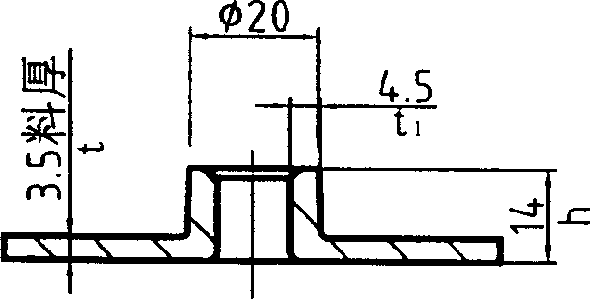
[0014] according to figure 1 As shown, the finished part is a chassis with a wall thickness of 3.5mm (the following measurement units are mm), the height of the boss is 14, the diameter of the boss is 20, and the wall thickness of the boss is 4.5. The process of the present invention produces the above-mentioned size parts, and the steps are as follows:

[0015] 1. Preforming: The workpiece plate is preformed into a convex shape by stamping, so that the difference volume is equal to the convex part, the height of the convex part is 26, the diameter is approximately hemisphere with a diameter of φ50, and the thickness remains unchanged;

[0016] 2. Stiff shape: the working diameter of the die is φ40, the mouth fillet is R8, the punch is φ30 and the height is 22. There is also a punching die φ6.8 inside the end to the fillet R7, and the hole punched out in the center of the workpiece is the subsequent positioning And the diameter of the pre-set hole.

[0017] Die work...

Embodiment 2

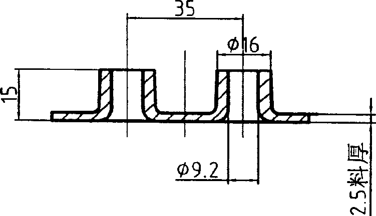
[0021] according to figure 2 As shown, the finished part is a chassis with a wall thickness of 2.5mm (the following measurement units are millimeters mm), with two bosses, the height of the boss is 15, the diameter of the boss is 16, the inner diameter is 9.2, and the center distance of the boss is 35 . The process of the present invention produces the above-mentioned size parts, and the steps are as follows:

[0022] 1. Preforming: Different from the general literature records, firstly, the punch and the sheet material form a 45° direction, and the two punches form a 90° angle between the same side of the sheet material, and the workpiece sheet is preformed by stamping. Cone, straight wall spacing 4. This scheme causes compressive stress to be first generated at the part of the workpiece that is easy to break, and the local material is replenished enough so that it will not crack when pulled. The flat center distance between the two punches of the second set of molds is s...


PUM

PropertyMeasurementUnit
thicknessaaaaaaaaaa
thicknessaaaaaaaaaa

Abstract

The invention provides a method for using punch technique to process the plate into wall-thickened work-piece. Via pre-molding the plate of work-piece into protruded shape, the differential volume is equal to the protruded part; using concave and protruding moulds to punch and shorten diameter of protruding part to make the height of work-piece equal to the pre-molded height; using one group of concave moulds whose diameters are constant-height continuous arranged to punch the outer diameter of protruding part and shorten the diameter of protruding part, therefore, the outer diameter of protruding part is the diameter of protruding cylinder of final product; using composite mould with expanding diameter and molding functions to make the diameter to the inner diameter of cylinder and compressing molding to reach the height of final product to attain the final product. The invention can solve the defects of present technique and integrate the plate chassis and the protruding cylinder, to confirm the strength demand of work-piece when in working, and improve service life of work-piece.

Description

technical field [0001] The invention relates to a metal stamping process, in particular discloses a method for processing a plate into a thickened workpiece with a raised cylinder wall by using the stamping process, and belongs to the technical field of metal parts processing technology. Background technique [0002] At present, for the production and processing of parts with special shapes, such as: there is a raised cylindrical workpiece on the plate-shaped chassis, and for the case where the thickness of the cylinder wall is greater than the thickness of the bottom plate, the conventional method is to process a single barrel-shaped workpiece The workpiece is fixed to the chassis by mechanical processing means (forging, welding, riveting, etc.) to form a whole workpiece. Since the workpiece is composed of two separate parts, there is a problem of stress concentration at the connection part, and it is easy to cause a problem from the root. Breaking affects the quality, serv...

Claims


Application Information

Patent Timeline
Patent Type & Authority Applications(China)
IPC IPC(8): B21D35/00
Inventor 夏勤三夏守仁
Owner 夏勤三
Learn More