Offshore platform hydraulic self-lifting device

A self-elevating technology for offshore platforms, applied in water conservancy projects, artificial islands, underwater structures, etc., can solve problems such as long construction work time, inconvenient operation, and inability to guarantee synchronous take-off and landing of pile legs, so as to save investment costs , fast locking effect

Active Publication Date: 2013-12-25
CHINA NAT OFFSHORE OIL CORP +1
View PDF7 Cites 10 Cited by
  • Summary
  • Abstract
  • Description
  • Claims
  • Application Information

AI Technical Summary

Problems solved by technology

[0003] When the height of the platform needs to be adjusted, it can be solved by lifting and lowering the platform block. At present, there is no specific solution for the platform in use in China. The method adopted by foreign companies is to first cut the pile legs, and then use the jacking device to lift them The platform block is lifted to a certain height, and then a new leg of the same size is inserted between the cut upper and lower legs, and fixed by welding, and finally the jacking device is unloaded. The disadvantage is that the construction process is complicated and needs to be separated Complete cutting, installation, welding and other operations; the operation is inconvenient, and the whole construction work takes a long time; the platform adjustment operation is easily affected by the sea conditions; the jacking device can increase the height of the pile legs, but it cannot guarantee the synchronization of each pile leg Take-off and landing; after the platform block is lifted, each leg rises to a different height, and new legs need to be adjusted separately before installing a new leg, which is time-consuming and laborious; the height of the raised platform is fixed and cannot be continuously adjusted. Can only repeat the above complex operation process again

Method used


Image

  • Offshore platform hydraulic self-lifting device
  • Offshore platform hydraulic self-lifting device
  • Offshore platform hydraulic self-lifting device

Examples


Embodiment Construction

[0038] The present invention will be further described below in conjunction with the accompanying drawings, but the present invention is not limited to the following embodiments.

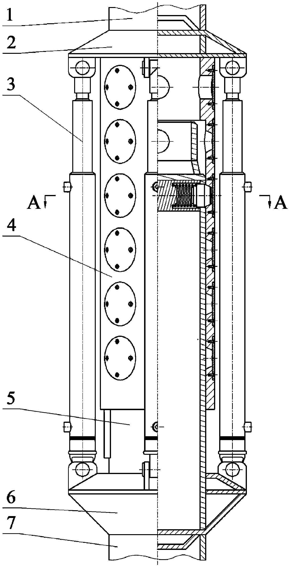
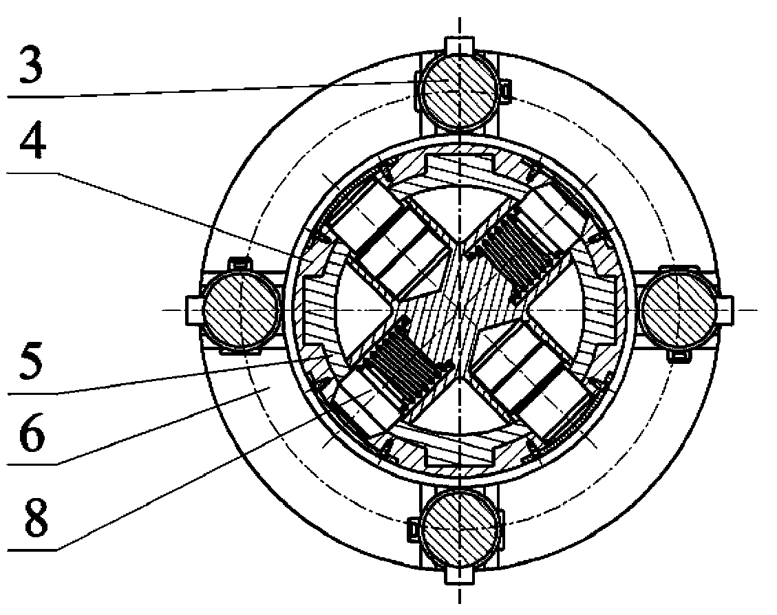
[0039] Such as figure 1 and figure 2 As shown, the offshore platform hydraulic self-elevating device provided by the present invention is the upper support 2, the hydraulic system 3, the sleeve assembly 4, the main body 5, the lower support 6 and the support body 8 on the upper part of the main body 5 from top to bottom. The upper support 2 and the sleeve assembly 4 are directly welded to the lower end of the platform leg 1 , and the body 5 and the support body 8 are directly welded to the upper end of the jacket leg 7 through the lower support 6 . Before the hydraulic self-elevating device is assembled, the outer surfaces of the upper support 2, the sleeve assembly 4, the body 5 and the lower support 6 are sprayed with paint to prevent corrosion of the device; the body 5 is placed in the sleeve a...


PUM


Abstract

The invention discloses an offshore platform hydraulic self-lifting device which comprises an upper support, a lower support, a sleeve assembly, a body, support body and a hydraulic system. The sleeve assembly comprises a sleeve. A plurality rows of circular holes are axially formed on the wall of the sleeve. Each row of circular holes comprises two symmetrical circular holes. At least two keyways are axially formed on the inner wall of the sleeve. The top of the sleeve is connected with the upper support. The body comprises a base pipe nested into a cavity of the sleeve. At least two guide grooves are formed on the outer wall of the base pipe. Wire guide grooves matched with the keyways can slide along the guide grooves. The bottom of the base pipe is connected with the lower support. The support body comprises a base block disposed on the upper portion of the base pipe and two support pins. The base blocks disposed in a cavity of the base pipe is connected with the base pipe. The support pins are connected with the base blocks. The pin bodies of the support pin penetrate the base pipe to be matched with the circular holes of the sleeve. The hydraulic system comprises at least two symmetric hydraulic cylinders which are connected to a main oil pump through multi-path reversing valves. The bottom of each hydraulic cylinder is connected with the lower support, and the top thereof is connected with the upper support.

Description

technical field [0001] The invention relates to a hydraulic self-elevating device for an offshore platform. Background technique [0002] In the development of offshore oilfields, in order to reduce investment costs, it is sometimes necessary to realize that the platform can operate in different areas (such as a movable platform), which involves the migration of the platform. Since the depth of different sea areas will vary, it is often necessary to design a A device that can quickly adjust the height of the platform, so that the platform can be reused. [0003] When the height of the platform needs to be adjusted, it can be solved by lifting and lowering the platform block. At present, there is no specific solution for the platform in use in China. The method adopted by foreign companies is to first cut the pile legs, and then use the jacking device to lift them The platform block is lifted to a certain height, and then a new leg of the same size is inserted between the cu...

Claims


Application Information

Patent Timeline
Patent Type & Authority Applications(China)
IPC IPC(8): E02B17/08E02B17/06
Inventor 刘新福王春升李新仲谭越陈国龙郑晓鹏张明尚超周超李博
Owner CHINA NAT OFFSHORE OIL CORP
Why Eureka
Try Eureka