Connection device for mounting energy-saving lamp
A connection device and technology for energy-saving lamps, applied in the direction of connection, coupling devices, incandescent lamps, etc., can solve the problems of increased cost, increased production and assembly steps, and limited selection range, etc., and achieve the effect of safe and fast use and simple structure
- Summary
- Abstract
- Description
- Claims
- Application Information
AI Technical Summary
Problems solved by technology
Method used
Image

Examples
Embodiment 1
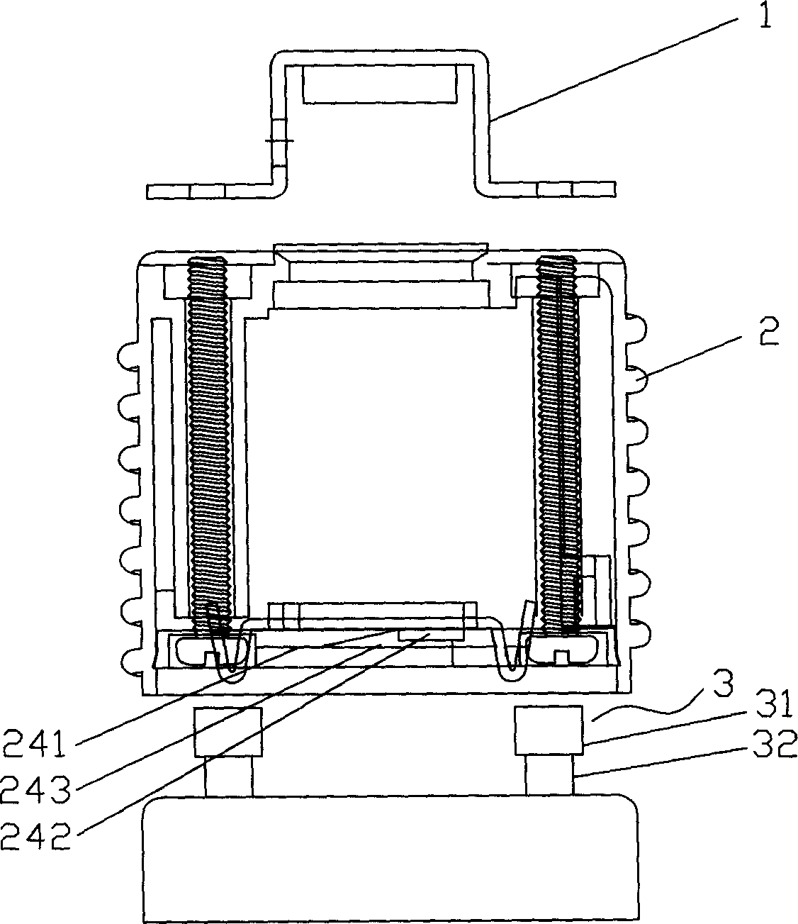
[0018] Such as figure 1 As shown, in this embodiment, the connecting device is a lamp socket 2 for installing an energy-saving lamp. One end of the lamp holder 2 is connected to a lamp, a wall, etc. through a fixing mechanism 1 , and the other end is provided with a jack suitable for the energy-saving lamp pin, which can be connected to the energy-saving lamp pin 3 .
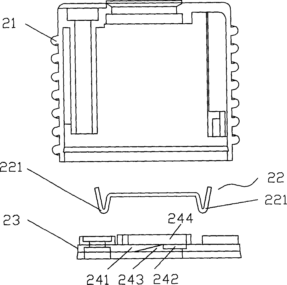
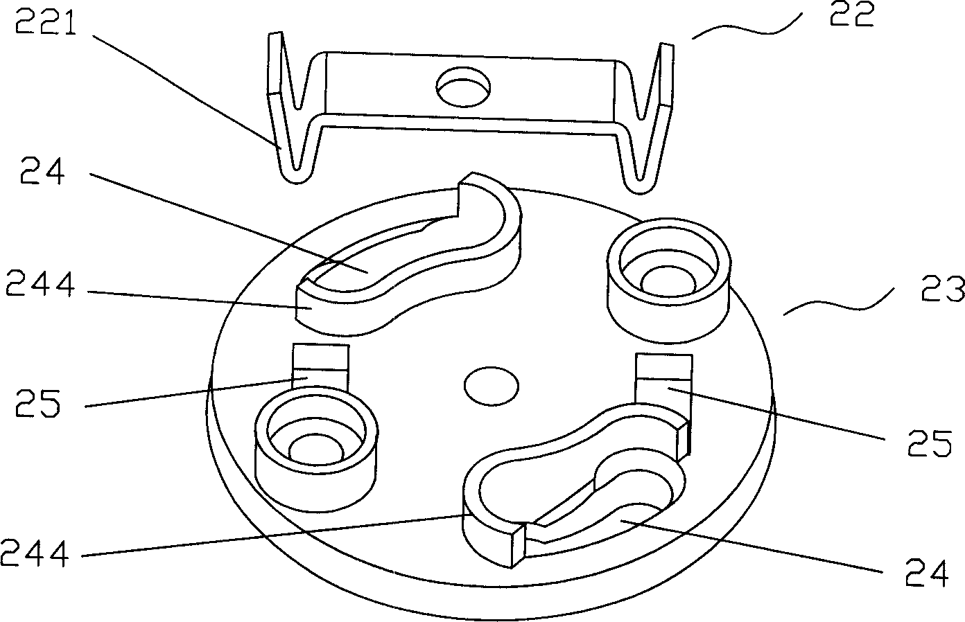
[0019] Such as figure 2 As shown in -4, the lamp holder 2 includes an insulating shell 21, an elastic device 22 and a jack plate 23. Two jacks 24 are provided on the jack plate 23, and the jacks 24 are arc-shaped and symmetrically arranged on the circumference with the center of the jack plate 23 as the center. One end of the socket 24 is an insertion end 241 whose width is larger than the diameter of the head 31 of the pin 3 , and the other end is a clamping end 242 whose width is smaller than the diameter of the head 31 of the pin 3 but larger than the diameter of the shaft 32 . A side of the jack 24 near ...
Embodiment 2
[0024] Such as Figure 5 As shown, in this embodiment, the connection device is a lamp cap conversion device 4 for installing energy-saving lamps. One end of the lamp cap conversion device 4 is screwed to a lamp holder suitable for an incandescent lamp, and the other end is provided with a jack suitable for the pin of an energy-saving lamp, which can be connected with the pin 3 of the energy-saving lamp.
[0025] The lamp cap conversion device 4 includes a conductive shell 41 , an elastic device 42 and an insertion hole plate 43 . The structure of the jack plate 43 is the same as that of the first embodiment. There are two arc-shaped sockets, and the inner surface between the insertion end 441 and the clamping end 442 of the socket is provided with an inwardly protruding blocking portion 443, and the lamp head conversion device 4 is fixed with an outwardly facing energy-saving lamp. The elastic device 42 of active force. The blocking portion 443 adopts a wedge-shaped protru...
PUM
 Abstract
Description
Claims
Application Information
 - R&D
- Intellectual Property
- Life Sciences
- Materials
- Tech Scout
- Unparalleled Data Quality
- Higher Quality Content
- 60% Fewer Hallucinations
Browse by: Latest US Patents, China's latest patents, Technical Efficacy Thesaurus, Application Domain, Technology Topic, Popular Technical Reports.
© 2025 PatSnap. All rights reserved.Legal|Privacy policy|Modern Slavery Act Transparency Statement|Sitemap|About US| Contact US: help@patsnap.com