Supercharge Your Innovation With Domain-Expert AI Agents!

Overpower protection device

一种过功率保护、过功率的技术,应用在紧急保护电路装置、输出功率的转换装置、直流功率输入变换为直流功率输出等方向,能够解决成本提高等问题

Active Publication Date: 2006-10-11
SYST GEN
View PDF0 Cites 9 Cited by
  • Summary
  • Abstract
  • Description
  • Claims
  • Application Information

AI Technical Summary

Problems solved by technology

That is to say, the known power supply must provide peak power for a certain period of time to these loads with motor characteristics, and the peak power is often more than a multiple of the maximum output power, resulting in the main power switch and some withstand voltage Current components must increase voltage and current stress, which in turn increases cost

Method used


Image

  • Overpower protection device
  • Overpower protection device
  • Overpower protection device

Examples


Embodiment Construction

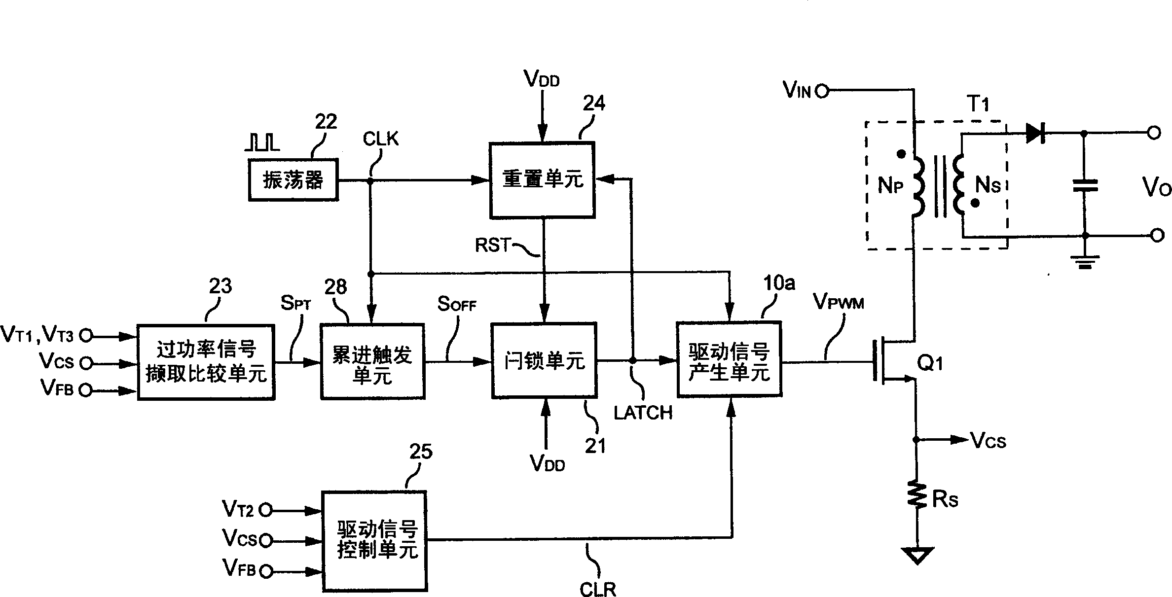
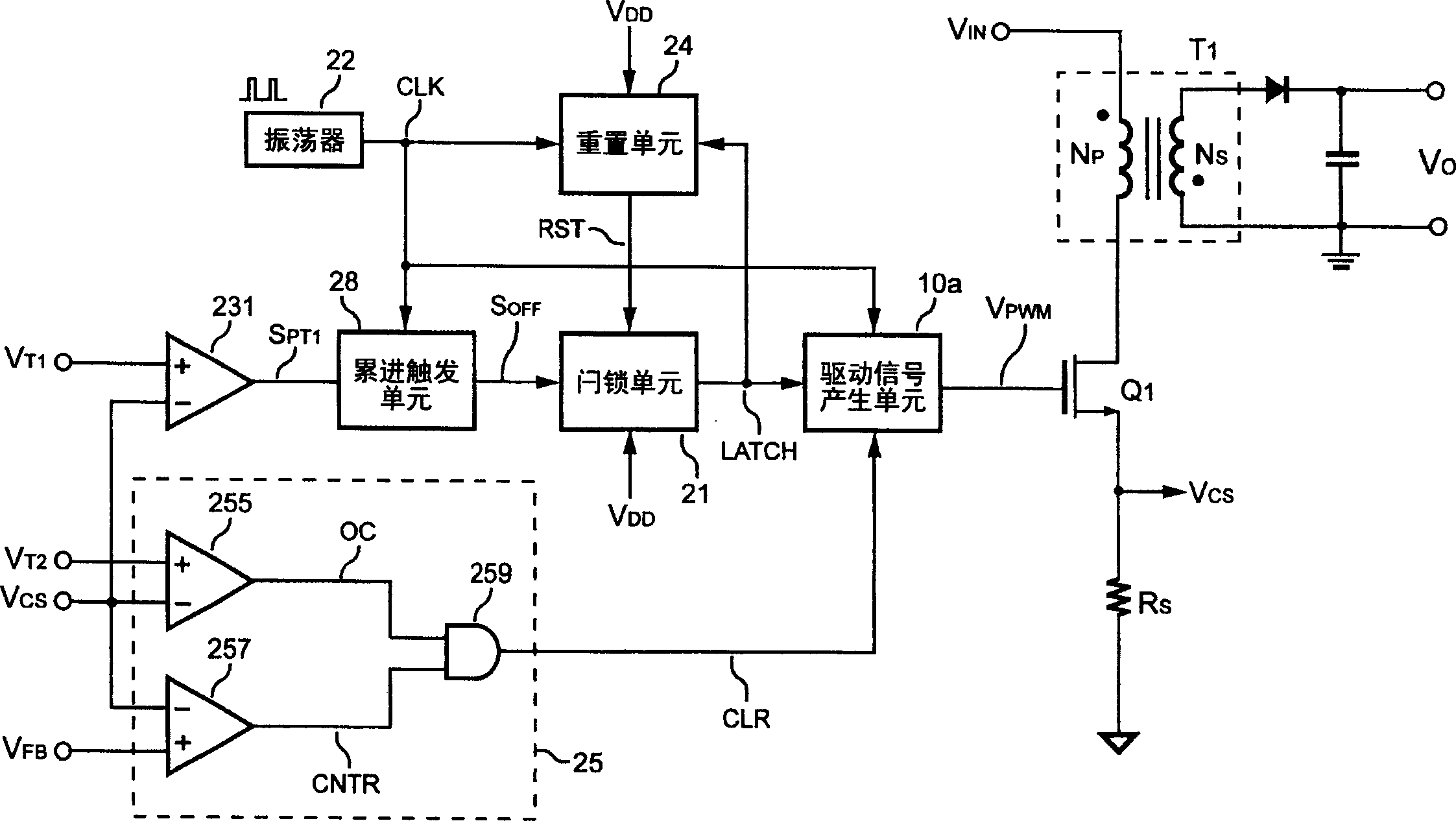
[0064] Please refer to figure 2 , is a schematic diagram of the circuit structure of the present invention. The over-power protection device of the present invention is used in a power supply, and includes: an over-power signal acquisition and comparison unit 23 extracts a sensing signal and compares it with a critical signal to generate a protection signal S PT ; A progressive trigger unit 28 is connected to the over-power signal acquisition and comparison unit 23 and an oscillator 22, and is used to receive the protection signal S according to a frequency signal CLK PT , with progressive count protection signal S PT , the protection signal S PT After the count reaches a default value, the incremental trigger unit 28 will output a cut-off signal S OFF ; A latch unit 21 is connected to the progressive trigger unit 28, receiving the cut-off signal S OFF , output a latch signal LATCH; a driving signal generating unit 10a is connected to the latch unit 21 and the oscillator ...


PUM


Abstract

The provided over-power protector comprises an oscillator to output frequency signal, an acquisition and comparison unit for over-power signal to output protective signal, an accumulated trigger unit connected between former two units to receive signal and output a terminal signal, a lock unit connected with last unit to receive the terminal signal and output a lock signal, a drive-signal producing unit connected between the lock unit and oscillator to receive the frequency signal and lock signal, and a drive-signal control unit connected to the last unit to receive the sensing signal and a second critical signal and output a clear signal to last unit to terminal the drive signal when the sensing signal up to the critical signal.

Description

technical field [0001] The invention relates to an overpower protection device, in particular to an overpower protection device applied to a power supply. Background technique [0002] At present, various power supplies are able to provide stable and regulated voltage and current. In order to comply with the consideration of safety regulations, the power supply must still provide an over-power protection function to ensure that the power supply itself and the power supply system are protected by limiting the output power during malfunctions such as overload, short circuit, and feedback open circuit. end. [0003] Please refer to figure 1 , is a schematic diagram of a known power supply. The power supply includes at least one transformer T 1 , a driving signal control unit 14, a driving signal generating unit 10, an oscillator 12 and a power switch Q 1 . Transformer T 1 Primary side switching current I P flow through the current sense resistor R S generates a current...

Claims


Application Information

Patent Timeline
Patent Type & Authority Applications(China)
IPC IPC(8): H02H7/122
CPCH02M1/32H02M3/33507
Inventor 杨大勇
Owner SYST GEN
Features
  • R&D
  • Intellectual Property
  • Life Sciences
  • Materials
  • Tech Scout
  • Unparalleled Data Quality
  • Higher Quality Content
  • 60% Fewer Hallucinations
Learn More