AI technical title is built by Patsnap AI team. It summarizes the technical point description of the patent document.
A multiplexer and circuit technology, which is applied in multiplexing communication, time division multiplexing systems, circuits, etc., can solve the problems of difficulty, power consumption, and difficulty in implementation.
Inactive Publication Date: 2006-10-11
TEST RES LAB
View PDF3 Cites 5 Cited by
Summary
Abstract
Description
Claims
Application Information
AI Technical Summary
This helps you quickly interpret patents by identifying the three key elements:
Problems solved by technology
Method used
Benefits of technology
Problems solved by technology
However, it is not easy to use ultra-high-speed clocks to correctly control pipeline operations, and it is difficult to achieve
Even if it can be realized, there will be a problem that the power consumption will increase
[0016] In addition, compared to the time shortened by pipelining the switching operation completed in a very short time of 200 ns, the time constant is extended due to the increase of the time constant caused by connecting multiple multiplexers in a tree form. The influence of time is large, and even if a plurality of multiplexers connected in a tree form are simply pipelined, the processing speed of the multiplexer circuit as a whole cannot be sufficiently improved.
Method used
Image
Click on the blue label to locate the original text in one second.
Reading with bidirectional positioning of images and text.
Examples
Embodiment Construction
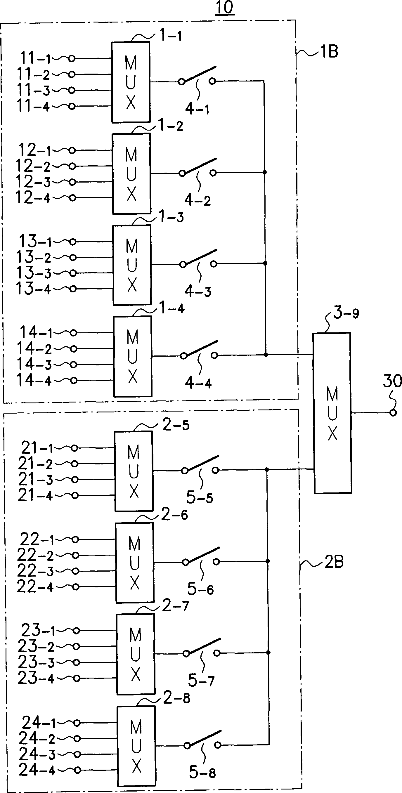
[0031] One embodiment of the present invention will be described below with reference to the accompanying drawings. image 3 This is a diagram for explaining a configuration example of the multiplexer circuit 10 in the present embodiment.
[0032] like image 3 As shown, the multiplexer circuit 10 of this embodiment includes a plurality of multiplexers 1 -1 ,1 -2 ,1 -3 ,1 -4 ,2 -5 ,2 -6 ,2 -7 ,2 -8 , 3 -9 , and connect them into a tree structure. Among them, the first to fourth multiplexers 1 -1 ~1 -4 and 5th to 8th multiplexer 2 -5 ~2 -8 Belongs to Tier 1, 9th Multiplexer 3 -9 It belongs to Tier 2, which is one level above it.
[0033] In the first layer, the first to fourth multiplexers 1 -1 ~1 -4 Belonging to the 1st block 1B, the 5th to the 8th multiplexer 2 -5 ~2 -8 It belongs to block 2 2B. The reason why multiplexer 1 belonging to the same layer 1 like this -1 ~1 -4 ,2 -5 ~2 -8 Dividing into a plurality of blocks is to allow the on-periods of a p...
PUM
Abstract
A relay switch is provided between the output terminal of the multiplexer in a certain level of the tree structure and the input terminal of the multiplexer in a level higher than the certain level, and will be connected with Among the multiplexers in a certain hierarchy, the relay switches connected to the multiplexers in the signal selection period are turned on, and the relay switches connected to other multiplexers are turned off. By doing this, the resistance component and capacitance component of the multiplexer whose relay switch is turned off are disconnected from the tree structure, thereby reducing the time constant that affects the operating speed of the multiplexer By setting the value of CR in this way, it is possible to prevent the slowdown of the operation speed of the entire multiplexer circuit due to an increase in the time constant.
Description
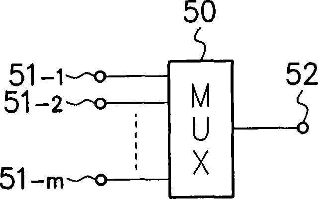
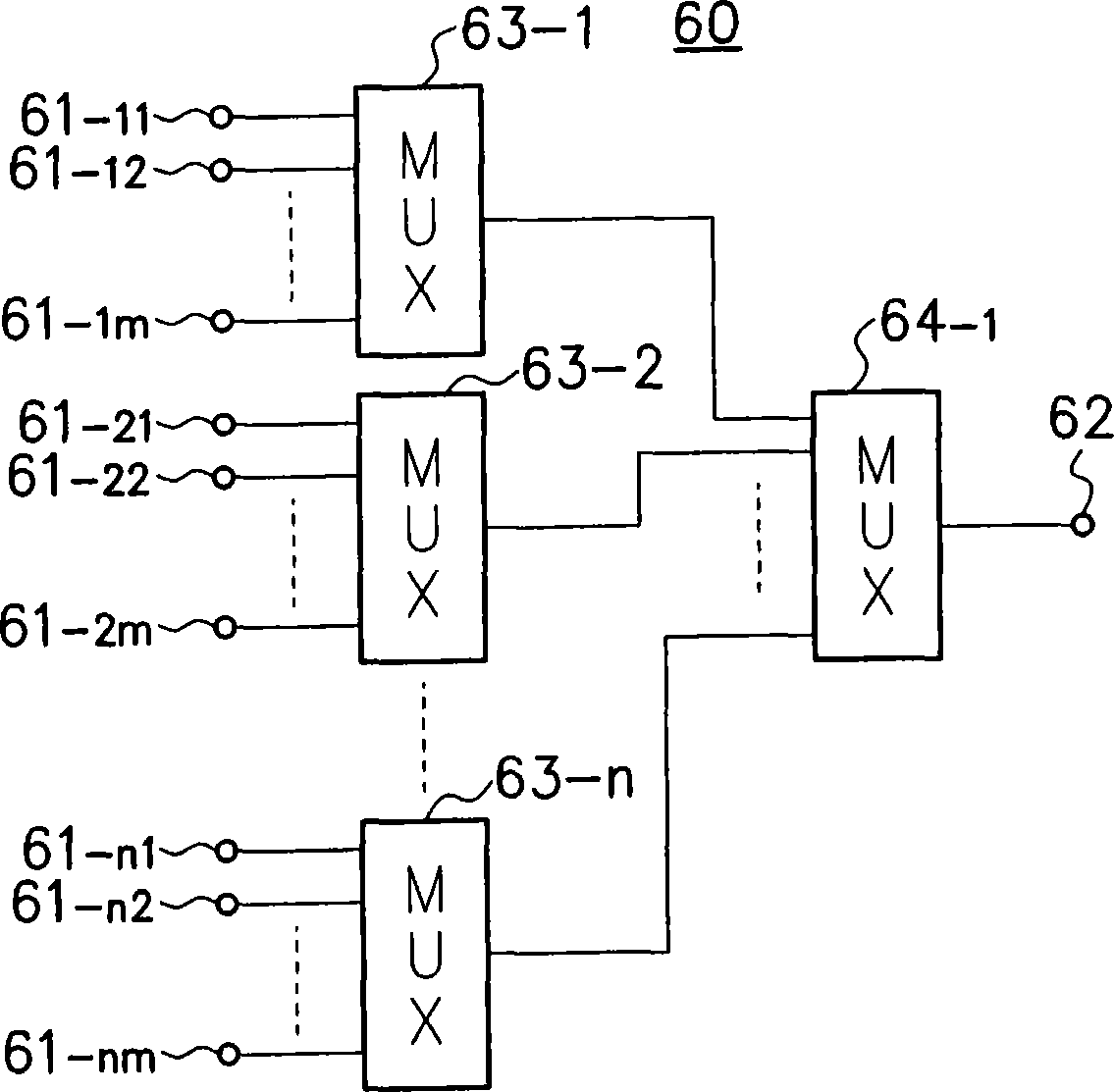
technical field [0001] The present invention relates to a multiplexer circuit that switches a plurality of signals input in parallel and selects them one by one and outputs them in series. Background technique [0002] like figure 1 As shown, a conventional general multiplexer circuit 50 sequentially switches the parallel load to a plurality of input terminals 51 -1 , 51 -2 , …, 51 -m The input signals are output from the output terminal 52 one by one as a serial signal. [0003] In addition, when the number of signals input in parallel is very large, a multiplexer circuit such as figure 2 shown, by combining multiple multiplexers 63 -1 , 63 -2 , …, 63 -n , 64 -1 tree-like connections. [0004] figure 2 In the multiplexer circuit 60 shown in the previous stage, a plurality of multiplexers 63 -1 , 63 -2 , …, 63 -n , switch in sequence and load in parallel to multiple input terminals 61 -11 , 61 -12 , …, 61 -1m ;61 -21 , 61 -22 , …, 61 -2m ;…;61 -n1 , 61 ...
Claims
Application Information
Patent Timeline
Application Date:The date an application was filed.
Publication Date:The date a patent or application was officially published.
First Publication Date:The earliest publication date of a patent with the same application number.
Issue Date:Publication date of the patent grant document.
PCT Entry Date:The Entry date of PCT National Phase.
Estimated Expiry Date:The statutory expiry date of a patent right according to the Patent Law, and it is the longest term of protection that the patent right can achieve without the termination of the patent right due to other reasons(Term extension factor has been taken into account ).
Invalid Date:Actual expiry date is based on effective date or publication date of legal transaction data of invalid patent.

