Device for regulating the operating pressure of an oil-injected compressor installation

A working pressure and compressor technology, applied in the field of working pressure devices, can solve the problems of staying in the pipe, compressed air loss, large input loss, etc., to achieve the effect of small time constant, easy realization, and improved efficiency

Active Publication Date: 2009-06-24
ATLAS COPCO AIRPOWER NV
View PDF1 Cites 5 Cited by
  • Summary
  • Abstract
  • Description
  • Claims
  • Application Information

AI Technical Summary

Problems solved by technology

[0004]The disadvantage of this pneumatic control system is that there is a continuous loss of compressed air, which is necessary for the good operation of this control system
[0005] Another drawback of this known pneumatic control system is that the operating pressure of the compressor unit when unloaded is always higher than when loaded, whereby in When the compressor unit is unloaded, the operating pressure requires more power from the engine
Another drawback of the [0006] known pneumatic control systems is that the regulation of the pressure tube and the air chamber creates a large time constant, so that the output flow of the compressor device suddenly In the event of fluctuations, there will be an "overshoot" or "undershoot" in the operating pressure, so that the operating pressure will suddenly exhibit very high or very low values ​​respectively
[0007] is associated with the disadvantage that the time constants mentioned above will have different values ​​when the dimensions of the regulating pressure pipe are changed (e.g. due to replacement or repair), This is detrimental to the stability of the regulation
An additional disadvantage of the [0008] known device is that condensation will form in the regulating pressure pipe of the pneumatic control system, which will be discharged through the air holes during the operation of the device, but Will remain in the pipe and may accumulate there when the compressor unit has been turned off
[0009] At sub-zero temperatures, the regulating pressure tubes also freeze and thus prevent the pneumatic control system from forming a good working condition
[0010]An additional disadvantage is that in the known device the required operating pressure is manually set by tightening the pneumatic regulating valve
Moreover, this setting can only occur during the operation of the compressor equipment
Another drawback of the [0011] known device is that the inlet valve is generally in the form of a piston valve, which is disadvantageous because its design results in large input losses

Method used


Image

  • Device for regulating the operating pressure of an oil-injected compressor installation
  • Device for regulating the operating pressure of an oil-injected compressor installation
  • Device for regulating the operating pressure of an oil-injected compressor installation

Examples


Embodiment Construction

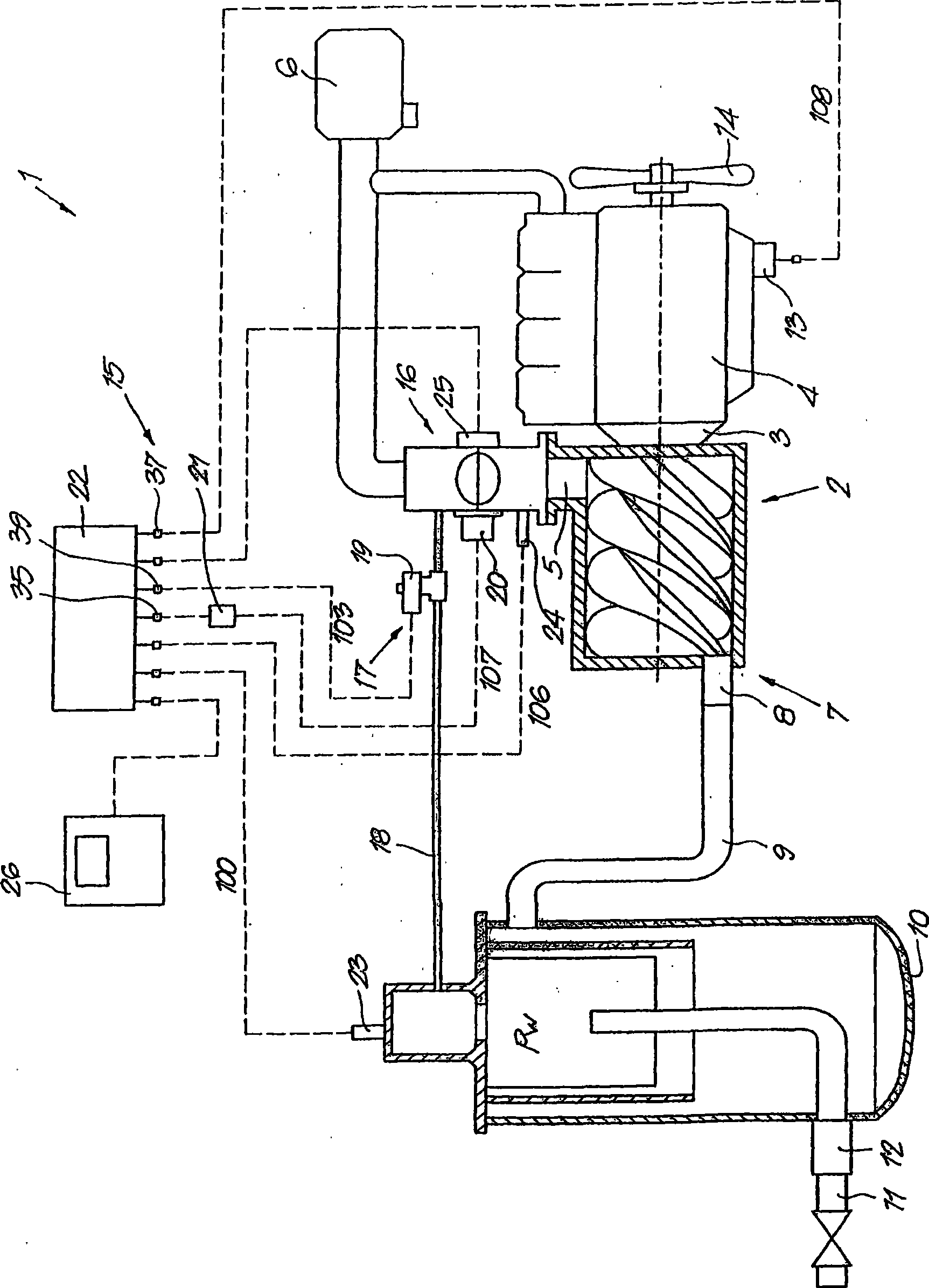
[0031] figure 1 A compressor device 1 is schematically depicted, which in this case is made in the form of an oil-injected screw compressor, which is provided with a compressor element 2 via a transmission 3 Driven by motor 4 with adjustable speed.

[0032] The compressor element 2 is provided with an air inlet 5 for introducing the gas to be compressed via an air filter 6 and a compressed air outlet 7 which opens through a non-return valve 8 in a duct 9 which is connected to a known type of oil separator 10.

[0033] Via a compressed air line 11, which is connected to the aforementioned oil separator 10 via a minimum pressure valve 12, the user of compressed air can take compressed air with a certain working pressure Pw and feed it, for example, into a compressed air network or the like .

[0034] The above-mentioned oil separator 10 passes through the injection pipe (not in figure 1 shown in ) is connected to an injection valve provided on the compressor element 2 to inj...


PUM


Abstract

Device for adjusting the operating pressure of an oil-injected compressor installation with a compressor element (2) driven by a motor (4) with an adjustable rotational speed and a control module (13), whereby the device (15) is provided with a controlled inlet valve (16) which is connected to the air inlet (5) and a blow-off mechanism (17) which can be closed by means of a blow-off valve (19), characterised in that the above-mentioned inlet valve (16), the blow-off valve (19) and the control module (13) are electrically controllable components which are connected to an electronic control unit (22) for adjusting the operating pressure (Pw), which is measured by an operating pressure sensor (23).

Description

technical field [0001] The invention relates to a device for regulating the operating pressure of oil-injected compressor installations. Background technique [0002] In EP 0 942 173 of the same applicant a device for regulating the operating pressure of an oil-injected compressor device provided with a compressor element driven by a motor has been disclosed , the motor is controlled by a control module and its speed can be adjusted, wherein the oil-injected compressor element is provided with an air inlet and a compressed air outlet, and the compressed air outlet is connected to an oil separator, and the oil separator has a A compressed air line supplying compressed air, wherein the device is provided with a controlled inlet valve connected to the above-mentioned air inlet port and a discharge mechanism with a discharge pipe connecting the oil separator and the inlet valve, and can be discharged through The valve is closed. [0003] In this known device, the inlet valve o...

Claims


Application Information

Patent Timeline
Patent Type & Authority Applications(China)
IPC IPC(8): F04C28/08
CPCF04B49/20F04B49/065F04B49/225F04C18/16F04C28/26
Inventor P·范登韦恩加特I·丹尼尔斯
Owner ATLAS COPCO AIRPOWER NV
Why Eureka
Try Eureka