Printing apparatus

A technology of printing device and supporting device, applied in the directions of printing, printing machine, rotary printing machine, etc., can solve problems such as stencil position deviation, and achieve the effect of good support and restraint of substrate tilt

Active Publication Date: 2006-10-18
YAMAHA MOTOR CO LTD
View PDF2 Cites 22 Cited by
  • Summary
  • Abstract
  • Description
  • Claims
  • Application Information

AI Technical Summary

Problems solved by technology

[0003] In this type of printing device, when the squeegee slides on the stencil to spread the s

Method used


Image

  • Printing apparatus
  • Printing apparatus
  • Printing apparatus

Examples


Embodiment Construction

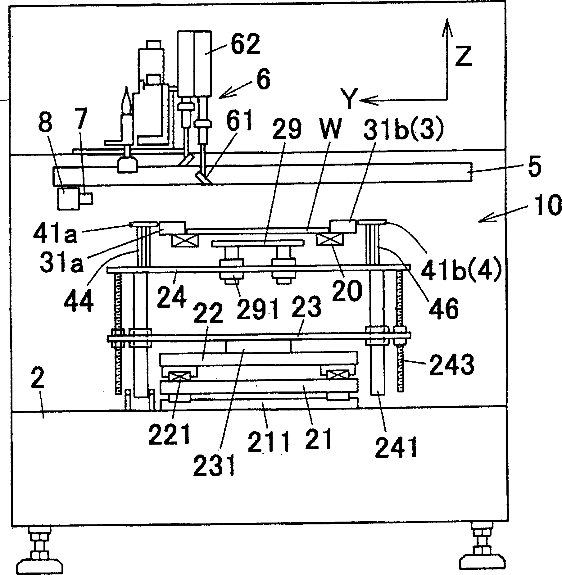
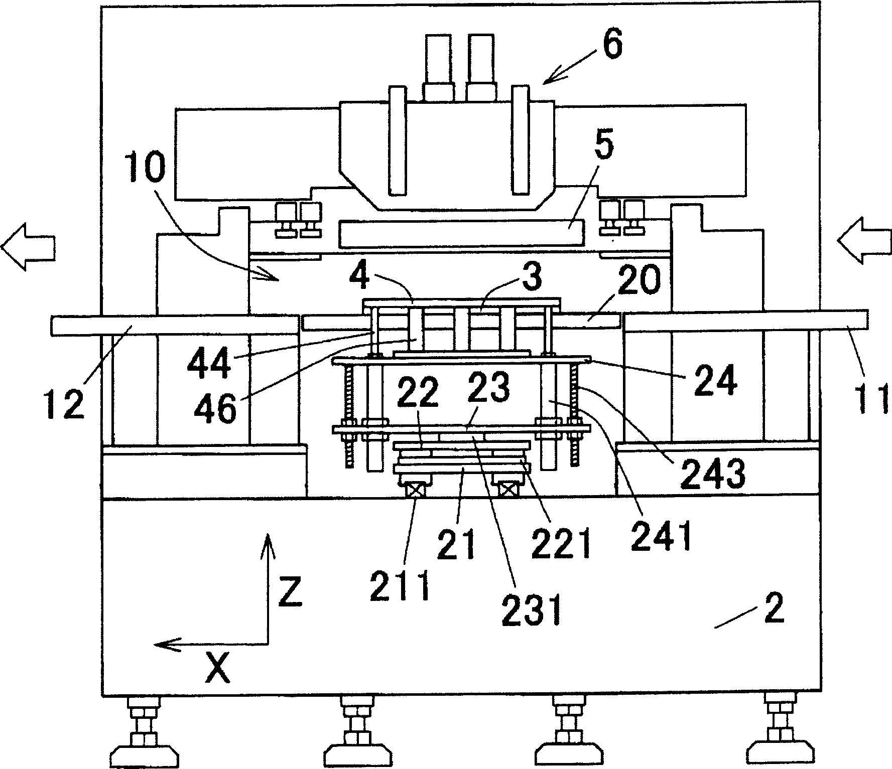
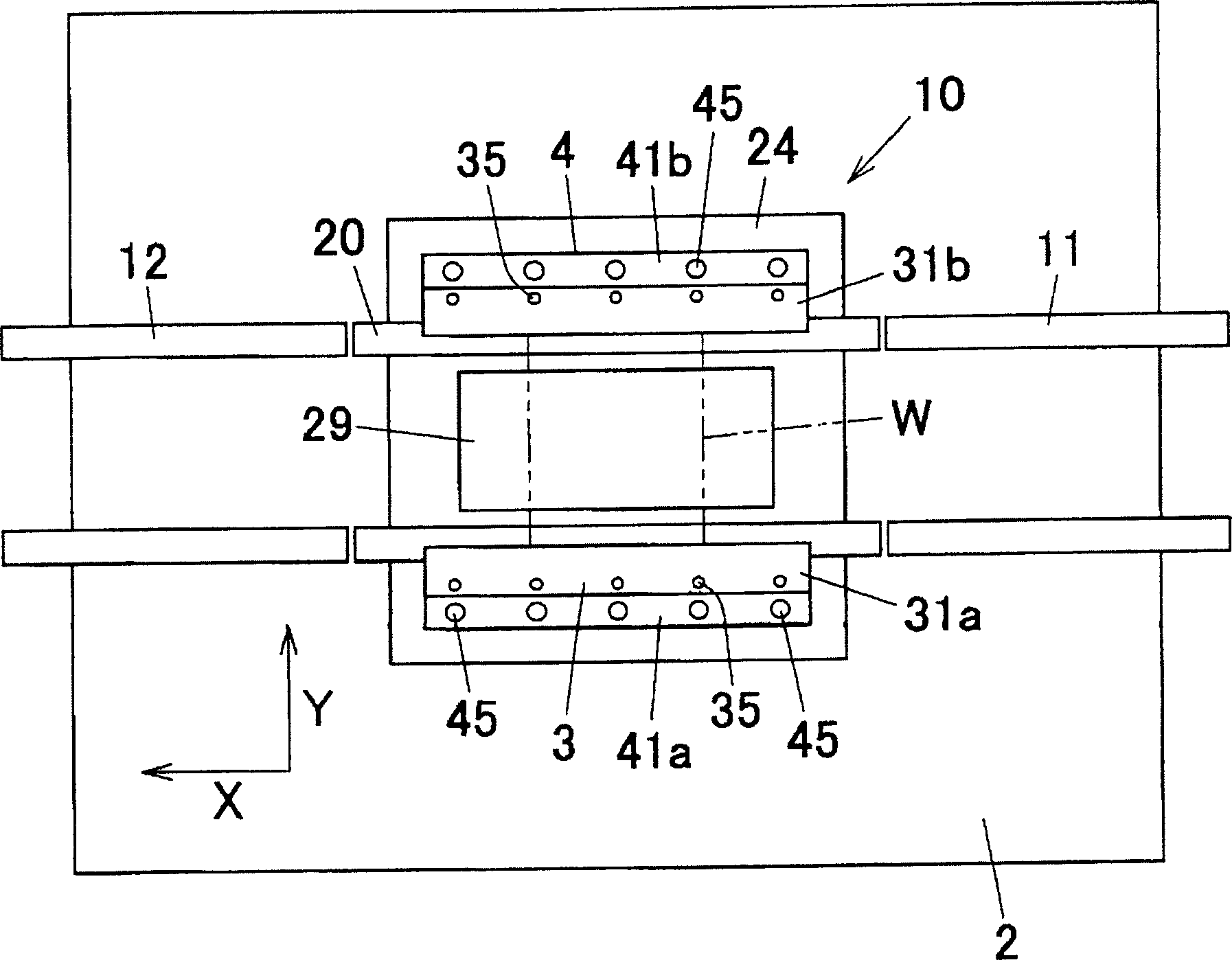
[0071] figure 1 is a side view of a screen printing device according to an embodiment of the present invention, figure 2 is the front view of the device, image 3 is the top view of the device, Figure 4 It is a perspective view of the main part (printing station 10) of this apparatus. As shown in these figures, a printing table 10 is provided on the base 2 of the screen printing apparatus, and on both sides of the printing table 10 , along the X-axis direction (conveyance direction), there are printed circuit boards for loading and unloading printed circuit boards W. The upstream side conveyor belt 11 and the downstream side conveyor belt 12 of the table 10 .

[0072] Moreover, the printing device includes: a clamp unit 3 for clamping the printed substrate W; a positioning unit 4 that engages with the upper surface of the substrate for positioning when clamping the substrate W; and a stencil holding unit arranged above the printing table 10 5 and the squeegee unit 6; as ...


PUM

PropertyMeasurementUnit
Thicknessaaaaaaaaaa

Abstract

The invention provides a printing device capable of ensuring a larger stencil adsorption area during printing. The printing device of the present invention includes: a pair of clips (31a), (31b) that clamp and hold the substrate (W) from both sides; when the substrate is held by the clips, a positioning device ( 41a, 41b); in the state that the positioning device (41a, 41b) is withdrawn from the substrate to the side, the stencil (51) arranged on the substrate held by a pair of clips (31a, 31b); Sliding on the stencil, the solder (S) on the stencil is spread and coated on the squeegee (61) on the substrate (W). A stencil (51) is placed on the positioning device in the retracted state, and a positioning device side suction device (45) for absorbing the stencil (51) is provided on the upper surface of the positioning devices (41a, 41b).

Description

technical field [0001] The present invention relates to a printing device for printing solder such as cream solder on a substrate. Background technique [0002] Conventionally, a stencil (mask) for screen printing is superimposed on a substrate fixed on a printing table, and solder such as cream solder supplied to the stencil is spread by a squeegee and passed through an opening (pattern hole) formed on the stencil. ) A screen printing device for printing (applying) solder on a predetermined position of a substrate is well known. [0003] In such a printing device, when the squeegee slides on the stencil to spread the solder, the frictional resistance generated by the squeegee may shift the position of the stencil. [0004] For this reason, in the screen printing devices shown in Patent Document 1 (Japanese Patent Laid-Open No. Hei 5-185580) and Patent Document 2 (Japanese Patent Laid-Open No. Hei 10-284829), clamps for holding the substrate from both sides are used. There...

Claims


Application Information

Patent Timeline
IPC IPC(8): B41F15/08B41F15/26B41F15/36B41F15/40H05K3/34
Inventor 楠木寿幸秋吉洋
Owner YAMAHA MOTOR CO LTD
Why Eureka
Try Eureka