Intelligent electrically controlled lock

An electronically controlled lock and intelligent technology, which is applied to building locks, non-mechanical transmission-operated locks, buildings, etc., can solve the problems of decreased safety protection performance, easy damage to the lock tongue, and failure to work normally.

Inactive Publication Date: 2006-10-18
钟坚波
View PDF0 Cites 4 Cited by
  • Summary
  • Abstract
  • Description
  • Claims
  • Application Information

AI Technical Summary

Problems solved by technology

However, although the traditional electronic control lock is practical, there are still the following disadvantages: (1), due to the mechanism, the door must be closed again after unlocking to lock it, otherwise it will remain unlocked forever, resulting in a decrease in safety protection performance; (2), the traditional electric lock The control lock relies on the energy storage of the spring to open the deadbolt. It takes a lot of force to close the door to compress the energy storage spring, so a door closer with a large closing force is required; (3). The sound of closing the door is very loud, disturbing the peace of the residents; (4), due to structural reasons, the unlocking structure of the traditional electric control lock is a light touch type, which is easy to cause a slightly larger door leaf vibration to cause false unlocking, and the safety performance is not enough; (5) Electromagnets are used to open the door of traditional electric locks, and the operating current of the electromagnets is as high as 4A or more. This not only increases the driving requirements of the control circuit, but also causes the arc of the control relay contacts to increase, which will cause The contact of the relay is sticky and the power cannot be cut off, and the electromagnet is energized for a long time and the electromagnet is burned
If a magnetic lock is used, it can solve the problem of closing noise and too much working current of the traditional electric lock, but the magnetic lock needs to be powered on for a long time, and the lock will be unlocked when the power is turned off, which consumes a lot of energy.
Although the silent lock launched in the market in 2000 solved the problem of closing noise and the burning of the electromagnet winding, the main problem was the high installation requirements, the limitations of use, and the unreasonable locking mechanism of the silent lock, which was easy to use and simple The method of opening is not safe enough, and there is also the disadvantage that the lock tongue is easily damaged. In addition, the instantaneous working current of the mute lock is much larger than that of the traditional electric control lock. Not only does the control circuit have high requirements, but it is also easy to damage.
But its locking process still lacks integrity, and there is a fatal "shortcoming" that is: whether it is unlocked or locked, the large deadbolt will pop out as the door leaf is pushed open or closed.
(If the user locks it, it can work normally) But when the user unlocks it, it will not work normally, and the big bolt will pop out, which will affect the inertia of the user's next door closing (coherence refers to: general The user closes the door after opening the door), but the "self-touch lock" cannot enable the user to close the door smoothly, and the user needs to manually retract the large bolt into the large lock shell to complete the function of locking and closing the door, which adds Unnecessary trouble for users
And the "new electric control lock" also has a "disadvantage" that is: the pop-up of the lock tongue is completely dependent on the motor as the power source
If it is disconnected from the electricity, it will not work properly
This will bother the user to manually retract the deadbolt into the large lock housing, which will undoubtedly add repeated troubles to the user.

Method used


Image

  • Intelligent electrically controlled lock
  • Intelligent electrically controlled lock
  • Intelligent electrically controlled lock

Examples


Embodiment Construction

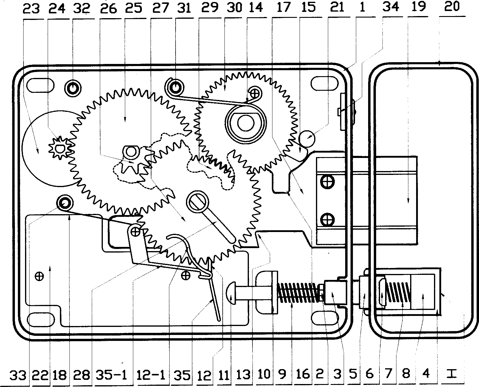
[0031] The present invention can adopt two types of automatic adjusters, that is, two parallel adjuster rollers 5, the rollers 5 are closely attached to the adjuster roller tray 6, and the tray 6 is supported by a tray spring 7. There are two adjuster tray positioning plates 8 at both ends of the bracket 4, which are used to control the deflection (or motion) stroke of the adjuster roller tray 6; Two pairs of "eight" shaped oblique waist grooves 49 li on the support both sides. Another form has an in-line groove 51 on both sides of the "凵" type regulator bracket 4, and the roller is a regulator double conjoined roller 5-1, which is connected in the middle of the regulator double conjoined roller 5-1. A roller vertical shaft 50, the two ends of this vertical shaft 50 are inserted in the in-line groove 51 of " 凵 " shape adjuster support 4 both sides. The structures of these two forms of autoregulators are somewhat different, but the effect of autoregulation is the same. In add...


PUM


Abstract

The present invention relates to lock manufacture, and is especially one kind of intelligent electrically controlled lock. The present invention proposes one automatic regulator and one automatic clutch mechanism to make the intelligent electrically controlled lock superior to available ones. It has novel structure design, easy manufacture, reliable operation, low noise and high safety performance. The intelligent electrically controlled lock includes large lock shell, control tongue and other parts, and features the automatic regulator inside a small lock shell and the automatic clutch mechanism connected to the large lock shell. The automatic regulator consists of rack, roller, tray, spring, positioning board and inclined middle groove; and the automatic clutch mechanism consists of driving gears, tongue positioning tab poker rod and connecting shaft.

Description

【Technical field】 [0001] The invention relates to a lock set combining electronics and machinery, in particular to an intelligent electric control lock, which is a mechanical-electrical integrated lock set and belongs to the hardware lock set manufacturing industry. 【technical background】 [0002] Traditional electric locks - mainly used for building intercom anti-theft systems and locks on anti-theft doors. Introduced into our country in the 1980s, it has simple structure, convenient installation and easy operation. It has become the main lock for the anti-theft door of the building intercom system, and it is widely used. However, although the traditional electronic control lock is practical, there are still the following disadvantages: (1), due to the mechanism, the door must be closed again after unlocking to lock it, otherwise it will remain unlocked forever, resulting in a decrease in safety protection performance; (2), the traditional electric lock The control lock r...

Claims


Application Information

Patent Timeline
Patent Type & Authority Applications(China)
IPC IPC(8): E05B47/02
Inventor 钟罗光钟坚波
Owner 钟坚波
Why Eureka
Try Eureka