Position sensing switch
A sensor switch and resistor technology, applied in the field of sensors, can solve the problem that the intelligent system is not easy to distinguish sensors, and achieve the effects of multiple functions, simple structure and improved reliability
- Summary
- Abstract
- Description
- Claims
- Application Information
AI Technical Summary
Problems solved by technology
Method used
Image
Examples
Embodiment 1
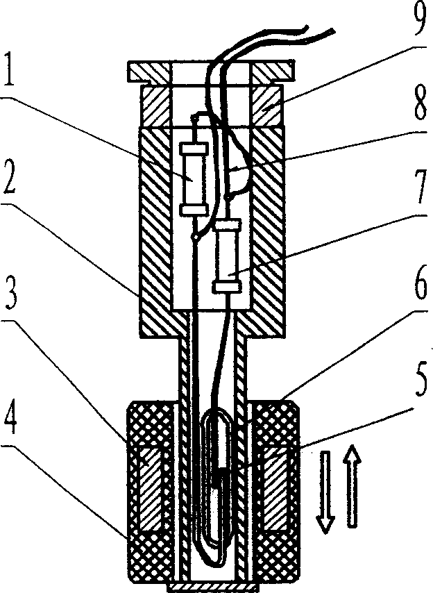
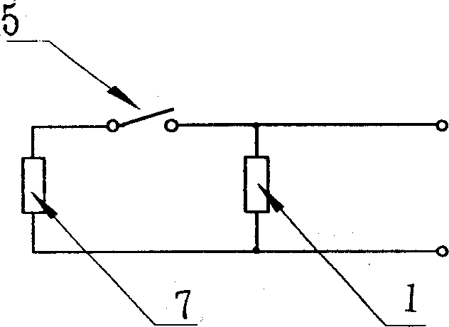
[0010] see figure 1 , figure 2 Shown, the present invention is made up of resistor A1, sleeve 2, permanent magnet 3, float 4, dry reed switch contact 5, dry reed switch 6, resistor B7, connecting wire 8, fixed seat 9, is in traditional The interior of the contact switch sensor is in accordance with the figure 1 space layout and figure 2 As shown in the electrical schematic diagram, a resistor is connected to both sides of the reed switch contact 5. Now take the magnetic induction contact switch type position sensor connection resistor as an example for the following detailed description: Resistor B7 and reed switch 6 In series, the resistor A1 is connected in parallel with the reed switch 6 and the resistor B7, the common end of the reed switch 6 and the resistor A1 is used as an output line of the sensor of the present invention, and the common end of the resistor A1 and the resistor B7 is used as the sensor of the present invention Another output line, by adding the abo...
Embodiment 2
[0011] Example 2: If Capacitor A and Capacitor B are used instead of Resistor A and Resistor B
[0012] see figure 1 , figure 2 As shown, a capacitor is connected to both sides of the reed switch contact 5, and the magnetic induction contact switch type position sensor connection capacitor is taken as an example for the following detailed description: the capacitor B7 is connected in series with the reed switch 6, and the capacitor A1 is connected to the reed switch. Tube 6 and capacitor B7 are connected in parallel. The common end of reed switch 6 and capacitor A1 is used as an output line of the sensor of the present invention, and the common end of capacitor A1 and capacitor B7 is used as another output line of the sensor of the present invention. By adding the above capacitor, the sensor of the present invention has the following output characteristics: when the reed switch contact 5 is disconnected, the sensor of the present invention presents the capacitive reactance ...
Embodiment 3
[0013] Example 3: If a pneumatic switch contact is used instead of a reed switch contact
[0014] according to figure 2 As shown in the electrical schematic diagram, the present invention is to connect a resistor on both sides of the pneumatic switch contact, and now take the connection resistor of the pneumatic switch contact position sensor as an example to make the following detailed description: the resistor B7 is connected to the pneumatic switch contact The points are connected in series, and the resistor A1 is connected in parallel with the pneumatic switch contact and the resistor B7. The common end of the pneumatic switch and the resistor A1 is used as an output line of the sensor of the present invention, and the common end of the resistor A1 and the resistor B7 is used as another output line of the sensor of the present invention. By adding the above resistor, the sensor of the present invention has the following output characteristics: the sensor of the present i...
PUM
 Abstract
Description
Claims
Application Information
 - R&D
- Intellectual Property
- Life Sciences
- Materials
- Tech Scout
- Unparalleled Data Quality
- Higher Quality Content
- 60% Fewer Hallucinations
Browse by: Latest US Patents, China's latest patents, Technical Efficacy Thesaurus, Application Domain, Technology Topic, Popular Technical Reports.
© 2025 PatSnap. All rights reserved.Legal|Privacy policy|Modern Slavery Act Transparency Statement|Sitemap|About US| Contact US: help@patsnap.com


