Supercharge Your Innovation With Domain-Expert AI Agents!

Ring oscillator for compensating voltage source offset

A ring oscillator and compensation voltage source technology, applied in power oscillators, electrical pulse generator circuits, electrical components, etc., can solve problems such as ring oscillator offset, achieve accurate oscillation frequency and eliminate errors

Inactive Publication Date: 2006-10-18
SUNPLUS TECH CO LTD
View PDF1 Cites 17 Cited by
  • Summary
  • Abstract
  • Description
  • Claims
  • Application Information

AI Technical Summary

Problems solved by technology

[0007] However, even with a constant voltage V CONST resistors with different temperature coefficients to accurately generate the current of the delay unit 27, the output frequency f of the ring oscillator 20 out still subject to the supply voltage V DD Effect of Offset

Method used


Image

  • Ring oscillator for compensating voltage source offset
  • Ring oscillator for compensating voltage source offset
  • Ring oscillator for compensating voltage source offset

Examples


Embodiment Construction

[0016] The ring oscillator for compensating voltage source offset of the present invention will be described in detail below with reference to the accompanying drawings.

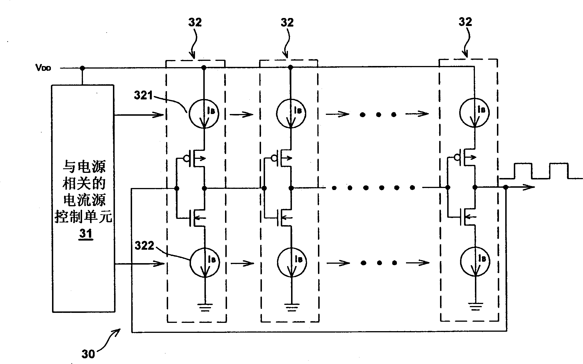
[0017] image 3 A ring oscillator that compensates for voltage source offsets for the present invention. As shown in the figure, the offset-compensated ring oscillator 30 utilizes a power-related current source control unit 31 to provide the current I of each delay unit 32 B , and make the current I B with supply voltage V DD It is linearly proportional. If the current of each delay unit 32 is I B (V DD ), the total capacitance value of each node of the ring oscillator 30 is C TOT , a total of N delay units 32, and the power supply voltage is V DD , then the output frequency f of the ring oscillator 30 of the present invention out for:

[0018] f out = I B ( ...


PUM


Abstract

A ring shaped oscillator compensating voltage source offset consists of a current source control unit for receiving a power supply voltage and outputting a current source control signal, multiple sets of ring shaped and series connected delay units as each unit being used to receive output signal of last stage and to output a delay signal. It is featured as using the first stage of delay unit to receive current source control signal and power supply voltage to make current in delay unit to power supply voltage be linear direct ratio to let output frequency of said oscillator not be influenced by offset of power supply voltage.

Description

technical field [0001] This invention relates to ring oscillators, and more particularly to ring oscillators that can compensate for voltage source offsets. Background technique [0002] A general current-starved ring oscillator requires a constant current basing scheme or a feedback loop to charge or discharge the current-controlled delay stage, and form a delay unit in the feedback loop to produce oscillations. figure 1 A circuit diagram of such a current-controlled ring oscillator. As shown in the figure, the ring oscillator 10 is composed of multiple (N) delay units 11 connected in series in a loop to form a feedback loop. Each delay unit 11 is composed of a current source 111 and transistors 112 , 113 . If the current provided by the current source 111 is I B , The total capacitance value of each node of the ring oscillator 10 is C TOT (assuming that the total capacitance value of each node is the same), there are N delay units 11, and the power supply voltage is V...

Claims


Application Information

Patent Timeline
Patent Type & Authority Applications(China)
IPC IPC(8): H03B5/04H03K3/011H03K3/03
Inventor 丁明強
Owner SUNPLUS TECH CO LTD
Features
  • R&D
  • Intellectual Property
  • Life Sciences
  • Materials
  • Tech Scout
  • Unparalleled Data Quality
  • Higher Quality Content
  • 60% Fewer Hallucinations
Learn More