Supercharge Your Innovation With Domain-Expert AI Agents!

Variable reluctance electric power system

a technology of electric power system and resistance, applied in the direction of dynamo-electric converter control, motor/generator/converter stopper, synchronous motor, etc., can solve the problems of high starting torque, difficult speed control, and low starting torque, and achieve low starting current, low cost, and high starting torque

Inactive Publication Date: 2007-07-05
HUGHES WILLIAM +2
View PDF5 Cites 0 Cited by
  • Summary
  • Abstract
  • Description
  • Claims
  • Application Information

AI Technical Summary

Benefits of technology

[0012] A relatively small direct current is passed through the field winding. This has the effect of creating north poles at one end of the lobes of the rotor and south poles at the other ends. By any of a number of conventional means, the current directed through the field coil may easily be controlled and, thus, the strength of the magnetic field created at the lobes of the rotor may easily be controlled.
[0015] In its motor configuration, the instant invention is the same as in the alternator description above except that the drive shaft powers any operating unit such as a wheel, gear or any other device which might be driven by an electric motor. In addition, the motor includes a sensor which instantaneously sense position of the rotor. The sense signals are then used to trigger a solid state inverter system, the output frequency of which is thus exactly synchronized with the rotor. Thus, the rotor speed controls the frequency of the solid state switching system.
[0021] Another objective of the present invention is to eliminate the high startup current requirement of conventional a-c electric motors.
[0022] Another objective of the present invention is to provide high starting torque.
[0023] Another objective of the present invention is to provide a variable reluctance electric power system which is simple, reliable, inexpensive, and easy to use and maintain.

Problems solved by technology

In spite of its popularity, the induction motor has several serious drawbacks including: its starting torque is very low, it requires six to eight times its rated full load current to start, and speed control is difficult and requires considerable auxiliary equipment to be accomplished effectively.
This rotor configuration makes them expensive to manufacture, expensive to maintain, and limits the speed at which the rotor can turn and keep the windings safely embedded.
Some d-c rotors have embedded magnets which reduces or eliminates some of these problems, but there is some degradation of performance.

Method used


Image

  • Variable reluctance electric power system
  • Variable reluctance electric power system
  • Variable reluctance electric power system

Examples


second embodiment

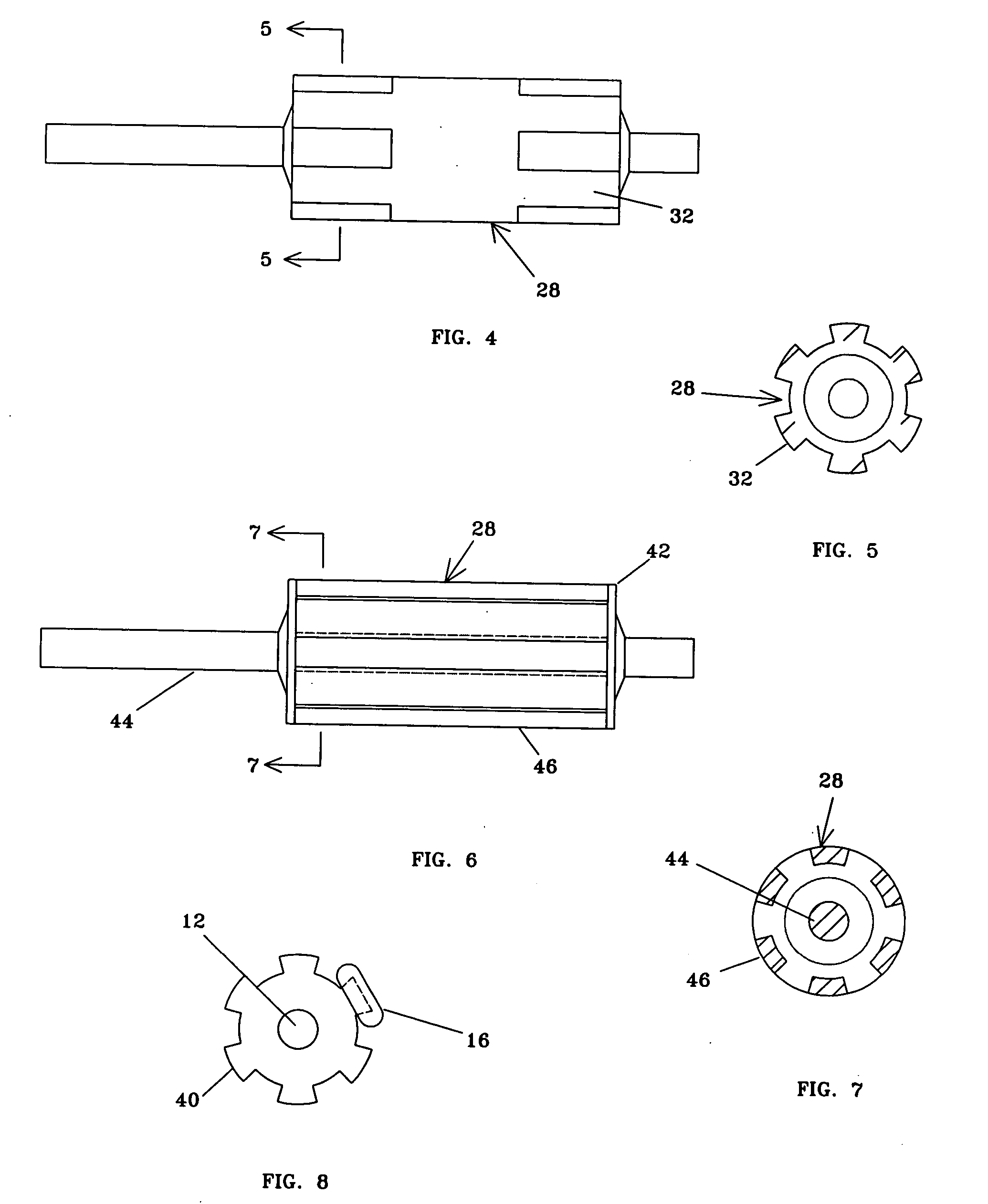
[0043] Referring now to FIG. 4, a side view of said rotor 28 is shown. As described above, said lobes 32 run the entire length of the body of said rotor 28. In the embodiment shown in FIG. 4, said lobes 32 do not run the length of said rotor 28, but occur only directly below said stators 34 (not shown in this Figure). It will be understood that shaping the poles of said rotor 28 may be used to provide an endless variety of wave shapes in the output of said stators 34.

[0044] Referring now to FIG. 5, a cross sectional view of the second embodiment of said rotor 28 taken along line 5-5 of FIG. 4 is shown. This Figure provides a better idea of the second configuration of said rotor 28. Said lobes 32 occur only at the ends of the body of said rotor 28. The center of said rotor 28 may be a solid cylinder or may be hollow.

third embodiment

[0045] Referring now to FIG. 6, a side view of said rotor 28 is shown which has the general configuration of a hollow squirrel cage. In this embodiment the body of said rotor 28 is not solid. A shaft 44 runs the length of said rotor 28 and a pair of end plates 42 are affixed to the shaft 44 at the position where the ends of the body of said rotor 28 would be in the previously described embodiments. Said lobes 32 (not present in this Figure) are replaced by a similarly configured series of bars 46 affixed between the two end plates 42. This embodiment would be useful and less expensive in lower speed machines. It may be necessary to include a central plate affixed to the center of said bars 46 to insure that said bars 46 do not bow outward.

[0046] Referring now to FIG. 7, a cross section view of the embodiment of said rotor 28 shown in FIG. 6 shown taken along line 7-7 of FIG. 6. This Figure better shows the configuration of said bars 46 and that the portion of said rotor 28 between s...

first embodiment

[0047] It should be understood that the embodiments of said rotor 28 shown in FIG. 4, 5, 6, and 7; work in exactly the same manner as described above for said rotor 28 and may be used in either the alternator configuration or the motor configuration of the instant invention.

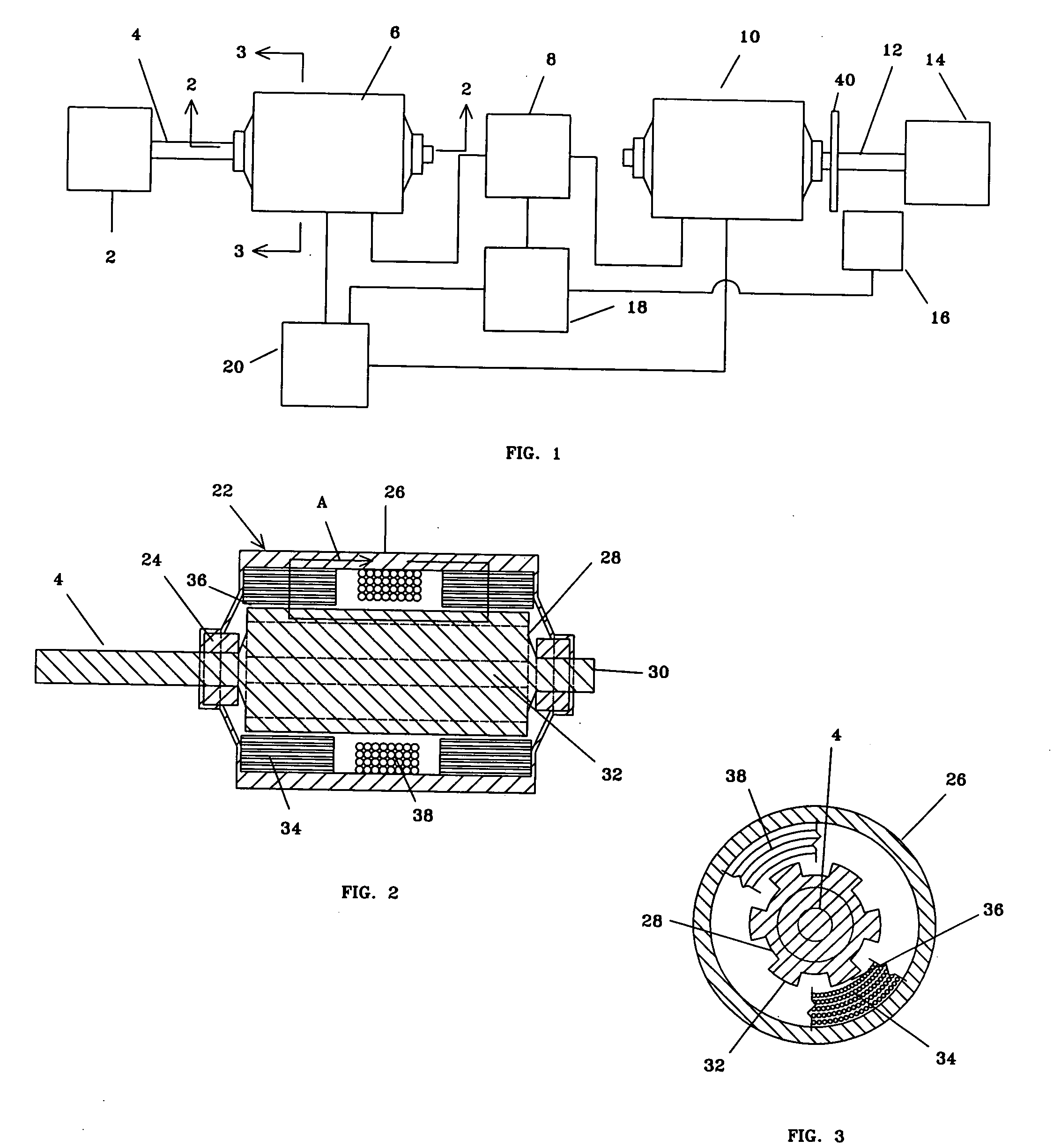
[0048] In operation, said prime mover 2 (which might be, for example, a turbine) turns said alternator shaft 4. The greatest benefits of the variable reluctance electric power system of the instant invention are realized if the operating speed of said prime mover 2 is significantly greater than the operating speed of said operating unit 14. For example, said prime mover 2 might be a turbine operating at 50,000 rpm and said operating unit 14 might be the drive wheel of a vehicle. In this example, the drive wheel would most likely operate at from zero rpm to less than 1,000 rpm. With a conventional system, the 50,000 rpm of the turbine would have to be mechanically reduced to the 0-1,000 rpm operating speed of the ...


PUM


Abstract

A variable reluctance electric power system which comprises an alternator and a motor having a rotor with longitudinal lobes and no windings, commutators, slip rings, magnets, or laminations. The alternator and the motor have stators which have conventional windings and laminations and a rotor which is polarized using a static field winding which surrounds but does not touch the rotor. The alternator and the motor may be coupled with current from the alternator driving the motor and solid state power devices controlling the frequency of the current to insure that the current from the alternator is always synchronized with the motor rotor.

Description

BACKGROUND OF THE INVENTION [0001] 1. Field of the Invention [0002] The present invention relates generally to electric power systems and more specifically to a variable reluctance electric power system which may be used as an alternator, a motor, or in combination. [0003] 2. Background Information [0004] In the United States and throughout the world, millions of people use electric motors and alternators on a daily basis. Conventional motors and alternators have a variety of configurations, but ordinarily consist of a metal case (usually steel), a stator which is secured inside the case, and a rotor which turns on bearings mounted at the ends of the case. There are other electric motor configurations, but a great majority have this configuration. A stator usually includes a series of laminations with interior windings, usually of copper wire. The laminations are insulated from each other, are stacked, and are configured so as to hold the stator windings within the interior of the s...

Claims


Application Information

Patent Timeline
Patent Type & Authority Applications(United States)
IPC IPC(8): H02P1/46
CPCB60K6/26Y02T10/642B60K6/46B60L2240/421B60W10/08B60W20/00B60W2710/06B60W2710/081H02K1/246H02K19/103H02K19/20H02K51/00Y02T10/6217Y02T10/641B60K6/405Y02T10/62Y02T10/64B60W10/06
Inventor HUGHES, WILLIAMGILMORE, LANCESTEICHEN, DUANE JOSEPH
Owner HUGHES WILLIAM
Features
  • R&D
  • Intellectual Property
  • Life Sciences
  • Materials
  • Tech Scout
  • Unparalleled Data Quality
  • Higher Quality Content
  • 60% Fewer Hallucinations
Learn More