

Dual-shaft variable-section roll-bending shaping machine
A technology of variable cross-section and forming machine, applied in the field of roll forming machine, which can solve the problem of single width, etc., achieve the effect of convenient operation, expanding the processing range and improving product quality
- Summary
- Abstract
- Description
- Claims
- Application Information
AI Technical Summary
Problems solved by technology
Method used
Image

Examples
Embodiment Construction
[0023] The present invention will be further described below in conjunction with the accompanying drawings and embodiments.
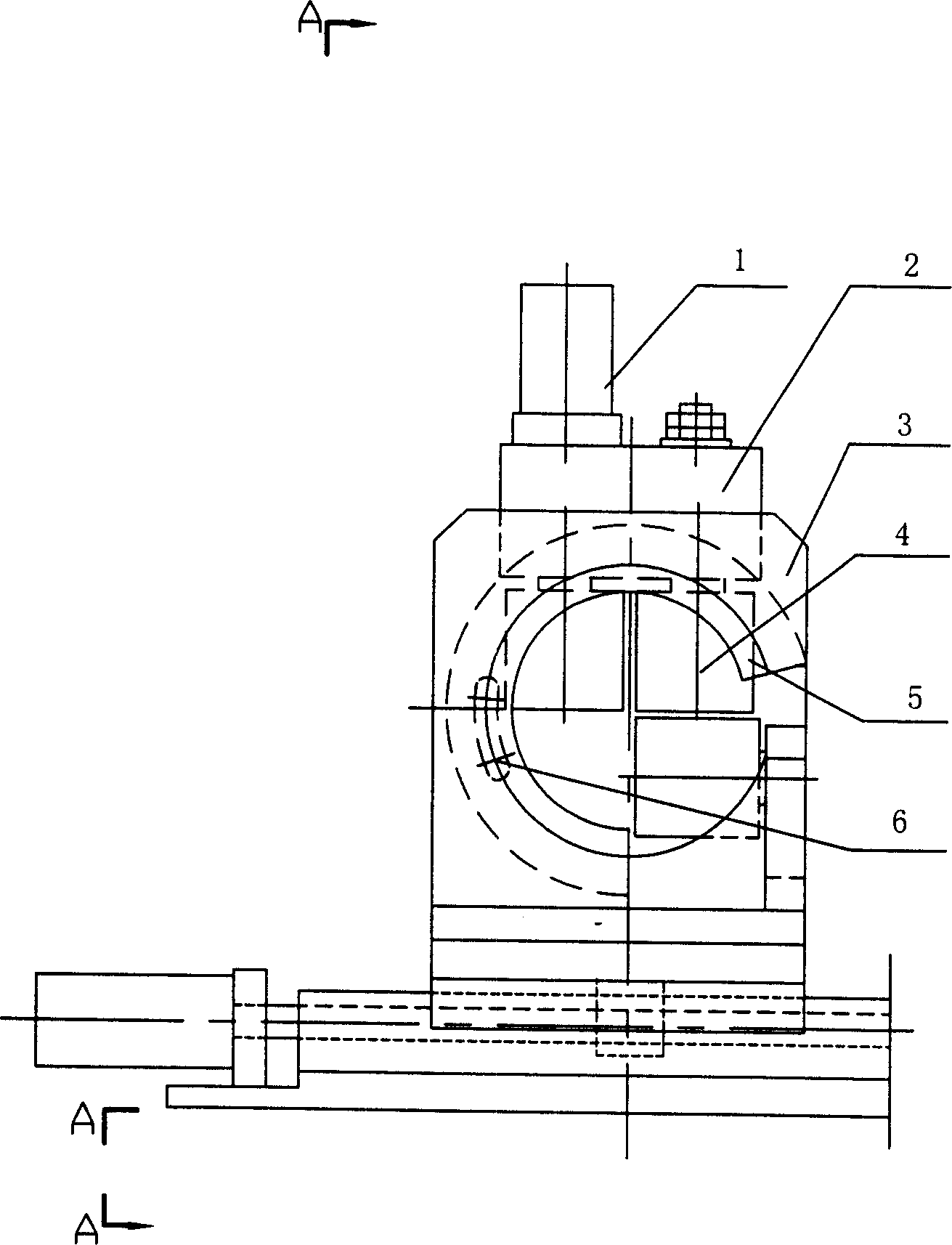
[0024] Such as figure 1 As shown, the forming machine of the present invention includes a motor 1, a guide rail 14, and a support, and the support includes a bearing block 2, a frame 3, a forming roller 4, and a support sleeve 5.
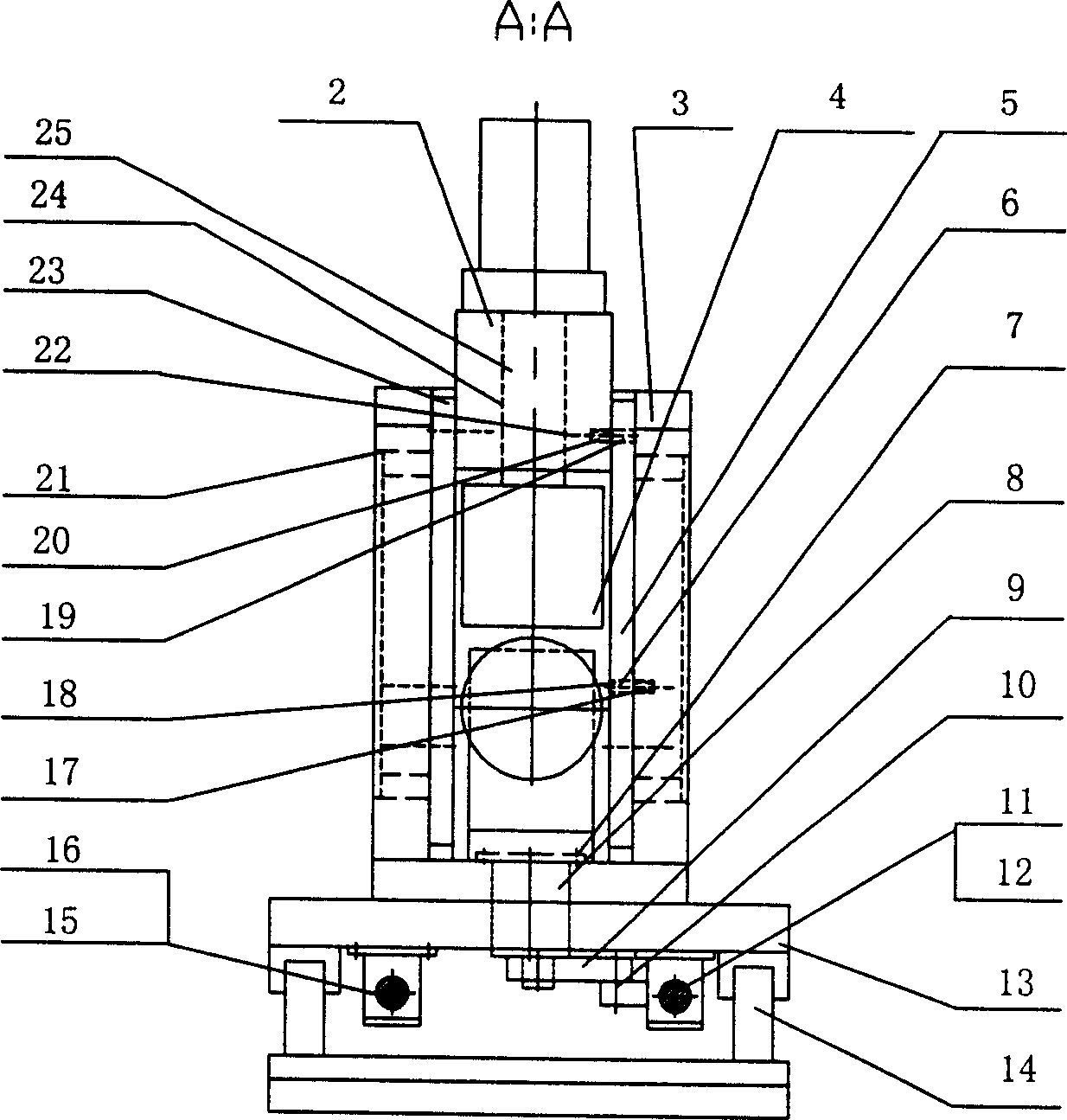
[0025] Such as figure 2 As shown, the end surface of the bearing seat 2 has a threaded hole 20, the flange 23 of the support sleeve 5 has a through hole 18, and the screw is screwed into the threaded hole 20 of the bearing seat 2 through the through hole 19 on the flange 23 of the support sleeve 5 The bearing housing 2 with the support sleeve 5 is formed. The support sleeve 5 is a part of the bearing seat 2 and has a flange 23. The support sleeve 5 is inserted into the hole 21 of the frame 3, and the two form a rotary pair. The flange 23 of the support sleeve 5 has a through hole 18, and the machine The part of the frame ...
PUM
 Abstract
Description
Claims
Application Information