Annular back-flow vertical wind tunnel, and its back-flow method

A wind tunnel and ring-shaped technology, applied in the field of vertical wind tunnels, can solve problems such as difficult heat dissipation, high temperature of internal return air, and restricted use, so as to prevent serious separation, reduce energy loss, and fresh air

Inactive Publication Date: 2006-10-25
刘晓萌
View PDF2 Cites 5 Cited by
  • Summary
  • Abstract
  • Description
  • Claims
  • Application Information

AI Technical Summary

Problems solved by technology

[0003] However, the existing vertical wind tunnels have the following disadvantages: open-circuit type (ie chimney type) is mostly used, although the structure is simple, but the height is high, the noise is high, and it is greatly affected by the external weather, which restricts its use; The design and construction of the return pipeline in the type return w

Method used


Image

  • Annular back-flow vertical wind tunnel, and its back-flow method
  • Annular back-flow vertical wind tunnel, and its back-flow method
  • Annular back-flow vertical wind tunnel, and its back-flow method

Examples


Embodiment Construction

[0020] The present invention will be further described below in conjunction with the accompanying drawings and embodiments, but it should be noted that these embodiments are only used to illustrate the solutions of the present invention, and should not limit the scope of the present invention thereto.

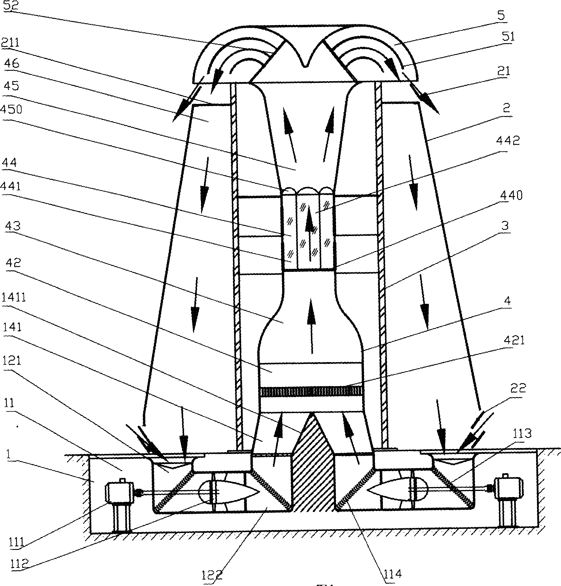
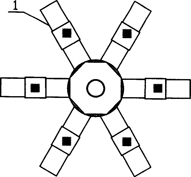
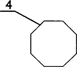
[0021] Such as figure 1 As shown, the annular backflow vertical wind tunnel of the present invention has the following parts: a lower power system 1 , a casing 2 , a bracket 3 , a working tunnel body 4 , and a backflow deflector 5 . The following describes the working principle of the system for these parts respectively.

[0022] In this embodiment, the power system of the present invention is different from the top-mounted power system of the existing wind tunnel, but the power system 1 is placed at the bottom of the entire vertical wind tunnel. Compared with the top-mounted power system, the advantage of this design is that Not only can the weight and vibration carried by th...


PUM


Abstract

The invention relates to a circuit plumping wind tunnel and the backflow method. The wind tunnel includes power includes power system and working tunnel identity. The working tunnel identity includes air intake end, stable section, contracted section, working section and air discharge end. The feature is that the wind tunnel contains a crust covering outside the working tunnel identity. A circle channel is set between the working tunnel identity and the crust. The air would blow from the air intake of the working tunnel identity and blow out form the air outlet of the working tunnel identity. The invention has low power request, easy to design and construct, low noise and could be used all weather. It is economy, safe, and confortabel.

Description


Claims


Application Information

Patent Timeline
Owner 刘晓萌
Why Eureka
Try Eureka