Optical disk drive focusing apparatus

A technology for optical disc drives, actuators, applied in packaging, head configuration/installation, recording/reproducing by optical methods, etc., which can solve problems such as performance degradation

Inactive Publication Date: 2006-10-25
HEWLETT PACKARD DEV CO LP
View PDF0 Cites 1 Cited by
  • Summary
  • Abstract
  • Description
  • Claims
  • Application Information

AI Technical Summary

Problems solved by technology

In the absence of effective closed-loop feedback circuitry, these sources of focus error can result in greatly degraded performance when marking images to the label side of the disc

Method used


Image

  • Optical disk drive focusing apparatus
  • Optical disk drive focusing apparatus
  • Optical disk drive focusing apparatus

Examples


Embodiment Construction

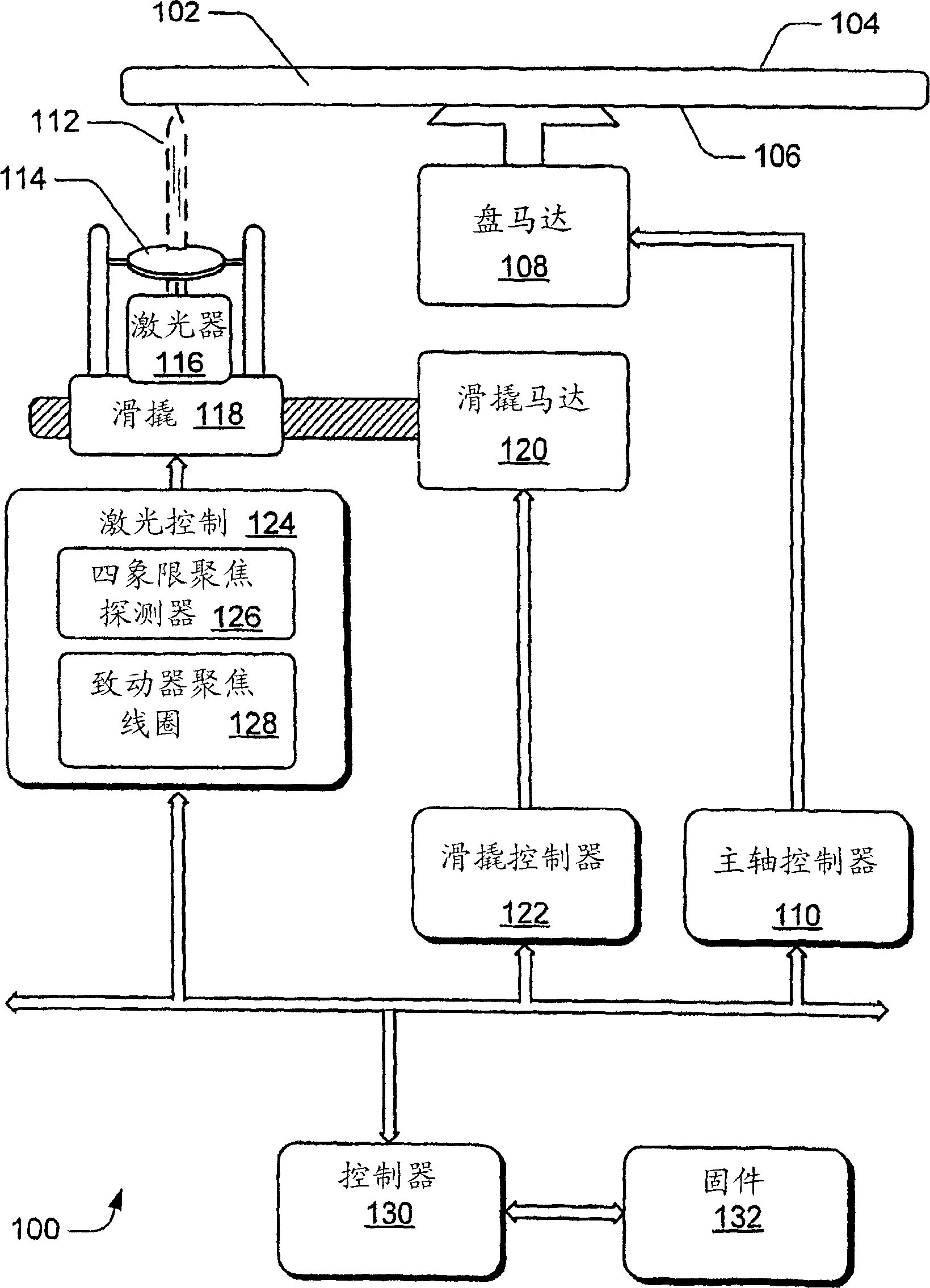
[0017] figure 1 A general schematic diagram of a typical disk drive and controller system 100 is shown. A disc 102 with an information side 104 is oriented to position a label side 106 for labeling. The disk is rotated by a disk or spindle motor 108 which is controlled by a spindle controller 110 . The laser beam 112 reaches the coated surface of the label side 106 of the disc 102 after passing through an optical system, such as a lens 114 . Laser 116 is carried by sled 118, and sled motor 120 moves the sled in a radial direction. In a typical application, sled motor 120 under the direction of sled controller 122 advances sled 118 carrying laser 116 in incremental steps from the radially inner edge of the label area to the radially outer edge of the label area.

[0018] Laser controller 124 controls the operation of laser 116 and associated tracking coils and detectors. exist figure 1 In the example of , the four-quadrant focusing detector 126 typically contains four dete...


PUM


Abstract

A system provides a signal to an actuator within an optical pickup unit of an optical disk drive. In one implementation, SUM signal data (an output from the quad sensors typically present in the optical pickup unit) is recorded within a SUM table. An error term generator processes the SUM signal data from the SUM table to produce an error term (step 506). An actuator control signal generator generates a signal to control movement of the actuator, wherein the signal is a function of a prior actuator position, the error term and an adaptation coefficient, wherein the adaptation coefficient impacts a rate at which the error term is allowed to modify the prior actuator position. This is used to focus on the label side of an optical disk to write an image (step 510).

Description

Background technique [0001] When reading or writing data to the data side of a CD, the traditionally used FES (Focus Error Signal) provides a closed-loop feedback circuit that allows operation to keep the optical pickup unit (OPU) in focus on the data pits, which is defined on the upper surface of the plastic layer. [0002] However, embossing technology enables writing on the label side of a CD, thereby producing an image, text and / or graphics. Unfortunately, traditional use of FES to focus on the disc label side is inefficient. [0003] The primary difficulty with focusing on the label side of the disc is that the FES signal provides a low signal-to-noise ratio, which is partly due to the nature of the medium used to cover the label side of the disc. Due to the low signal-to-noise ratio, conventional use of the FES signal set in a closed-loop feedback circuit will not efficiently signal the actuator coil for the converging point. [0004] A second difficulty with using th...

Claims


Application Information

Patent Timeline
IPC IPC(8): G11B23/40G11B7/0037G11B7/09
CPCG11B7/0037G11B7/0908G11B7/0945G11B7/09
Inventor D·M·汉克斯M·萨尔科A·L·范布洛克林
Owner HEWLETT PACKARD DEV CO LP
Why Eureka
Try Eureka