Cleaning robot having auto-return function to charching-stand and method using the same

A cleaning robot and automatic return technology, applied in the field of cleaning robots, can solve problems such as lowering

A cleaning robot and automatic return technology, applied in the field of cleaning robots, can solve problems such as lowering

CN1853552AInactive Publication Date: 2006-11-01LG ELECTRONICS INC

Image

  • Cleaning robot having auto-return function to charching-stand and method using the same
  • Cleaning robot having auto-return function to charching-stand and method using the same
  • Cleaning robot having auto-return function to charching-stand and method using the same

Examples


Embodiment Construction

[0023] Now, preferred embodiments of the present invention will be described with reference to the accompanying drawings.

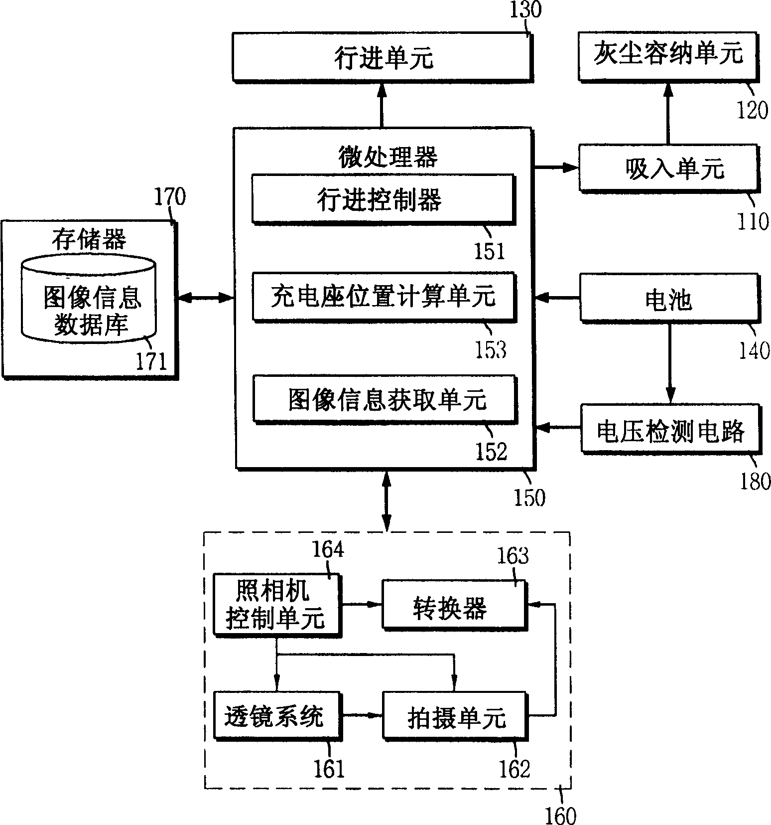
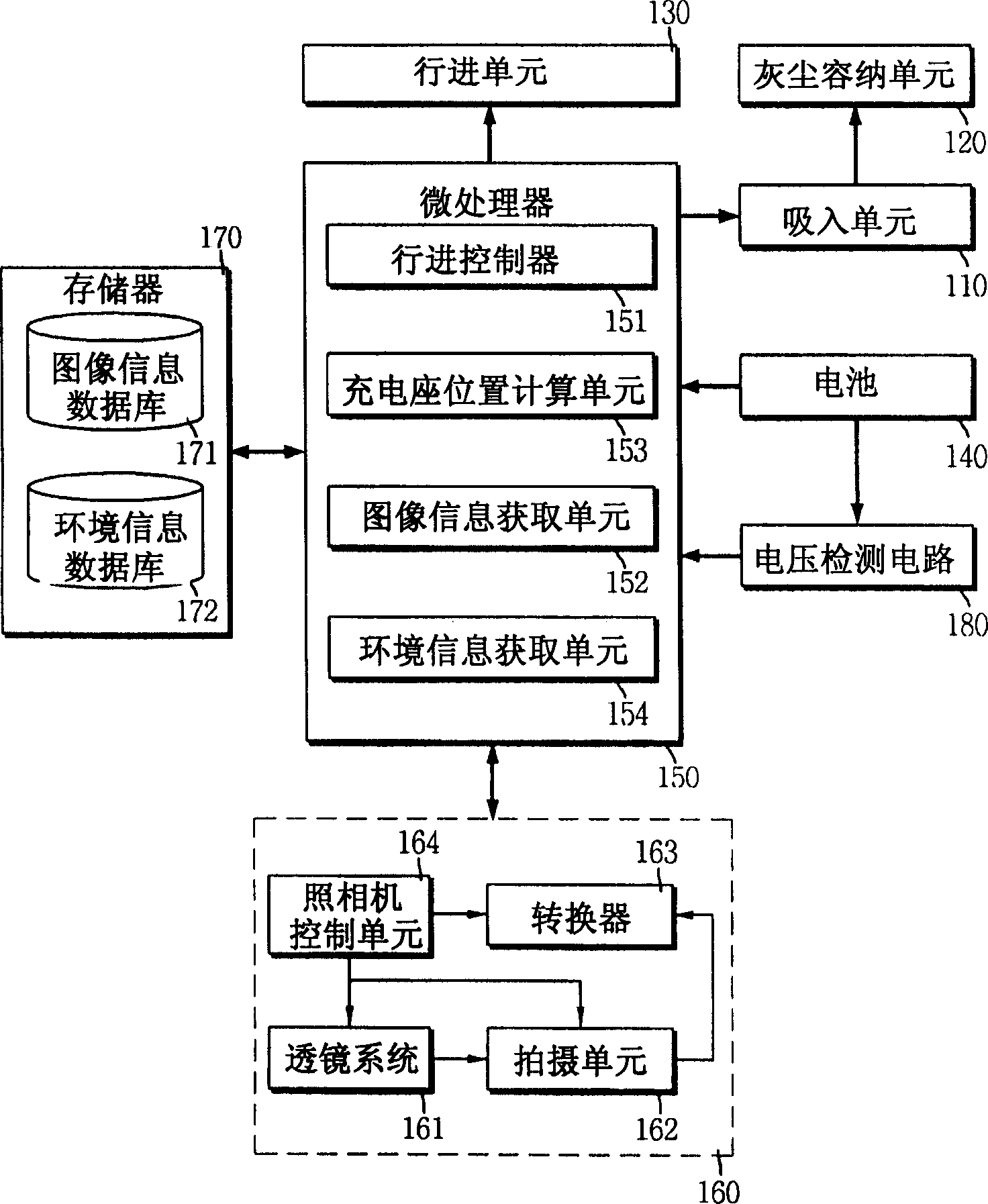
[0024] figure 1 is a schematic diagram illustrating a cleaning robot having a function of automatically returning to a charging stand according to a preferred embodiment of the present invention. As shown, the cleaning robot includes a common basic structure of conventional cleaning robots. In addition, the cleaning robot includes a camera unit 160 for outputting an image input from the lens; a memory 170 for storing an operation program to drive the cleaning robot and containing an image information database 171 for storing image information of a charging stand; battery voltage detection A circuit 180 for detecting the voltage of the battery 140 in the cleaning robot and outputting a charging request signal when the detected voltage of the battery 140 is lower than a reference value; and a microprocessor 150 for controlling the above components.

[002...


PUM


Abstract

A cleaning robot, and more particularly a cleaning robot comprising a camera unit for photographing an external image containing the charging-stand image, converting it into electrical image information, and outputting externally; and a microprocessor for storing the image information inputted the camera unit, acquiring position information of the charging-stand from the external image on the basis of the image information of the charging-stand in detecting a return signal, and causing the cleaning robot to be returned to the charging-stand. The cleaning robot having an auto-return function to a charging-stand detects a direction and position of the charging-stand using image information of the charging-stand, and thereby correctly and rapidly returning to the charging-stand for the cleaning robot.

Description

technical field [0001] The present invention relates to a cleaning robot, and more particularly to a cleaning robot having a function of automatically returning to a charging-stand, wherein the cleaning robot can correctly and quickly return to the charging-stand of the cleaning robot using image information input from a camera, and a method of use thereof . Background technique [0002] A cleaning robot is a device that autonomously moves in a defined cleaning area such as a residence and an office, and sucks in dust or impurities. The cleaning robot includes components of a general purpose vacuum cleaner as well as other components. Here, other components include a traveling device for making the cleaning robot travel; many sensors for detecting collisions of the cleaning robot so that it runs without colliding with various obstacles; and a microprocessor for controlling the above-mentioned cleaning robot. member. As it moves autonomously within the cleaning area, the c...

Claims


Application Information

Patent Timeline
01 Nov 2006
Publication
CN1853552A
IPC
A47L9/19; A47L9/28; B25J5/00; B25J13/08; G06T1/00
CPC
G05D1/0225; G05D1/0246; A47L7/0038
Inventors
郑一均