
Vision checking and calibrating method

A technology of visual acuity detection and visual acuity, applied in comprehensive refractometers, eye testing equipment, medical science, etc., can solve problems such as inability to fully correct myopia, inability to perform self-inspection, long correction time, etc.

Inactive Publication Date: 2006-11-01
赵进捷
View PDF0 Cites 14 Cited by
  • Summary
  • Abstract
  • Description
  • Claims
  • Application Information

AI Technical Summary

Problems solved by technology

Usually only a few light-emitting diodes form an optotype, and each group of optotypes lights up alternately or simultaneously, and then forms an optotype image through the refraction and reflection of single, double, and three-sided mirrors. Using this type of correction device has a small field of view and minimal eye movement. , It takes a long time to correct. This type of correction device cannot fully exercise and exercise the various organs of the eye, and cannot fully improve the blood circulation of the eye organs, metabolism and strengthen the function of each exercise muscle, so it cannot fully correct myopia, strabismus, amblyopia and Presbyopia and other visual impairment invention content
The commonly used visual acuity test method is obtained by the testee standing at a certain distance to distinguish the up, down, left, and right graphic directions on the "eye chart". It requires a special person to serve the testee and cannot perform self-testing.

Method used


Image

  • Vision checking and calibrating method
  • Vision checking and calibrating method

Examples


Embodiment Construction

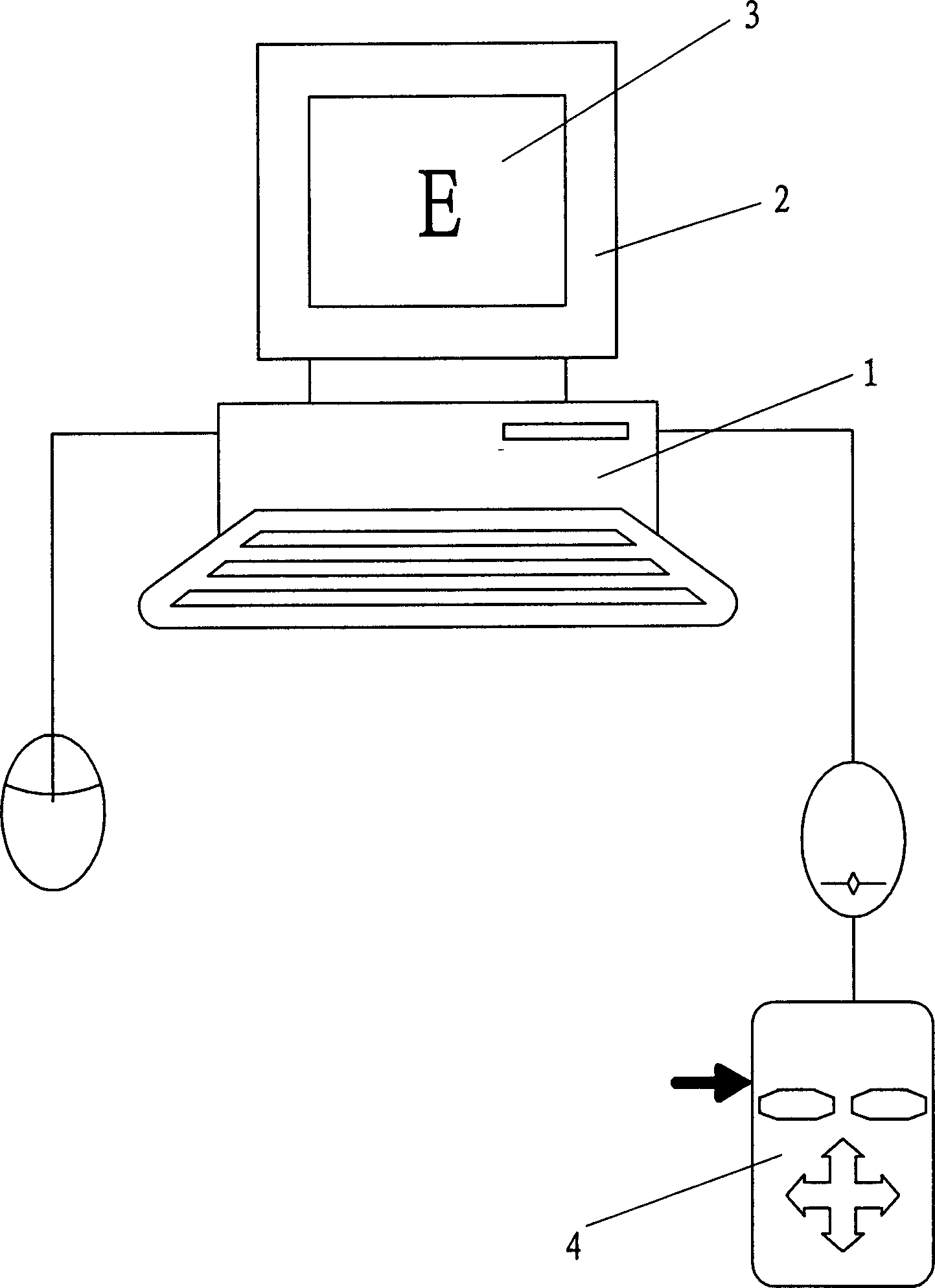
[0013] Such as figure 1 Shown, the present invention is a kind of visual acuity detection method, and this method is stored in control program and database in computer host computer 1, and visual acuity detection " E " image 3 (also can be other detection images) is displayed on display screen 2, and its " The size of the E" image 3 is generated step by step according to the size of the eye chart from 0.1 to 1.0, and the image direction is generated in a random manner. Image, input the up, down, left and right signals corresponding to the "E" image 3 to the host computer 1 through the infrared remote controller 4, and the visual acuity when two wrong signals are continuously input is the visual acuity index of the testee.

[0014] The infrared remote controller 4 as controller also can be replaced by mouse and keyboard etc.

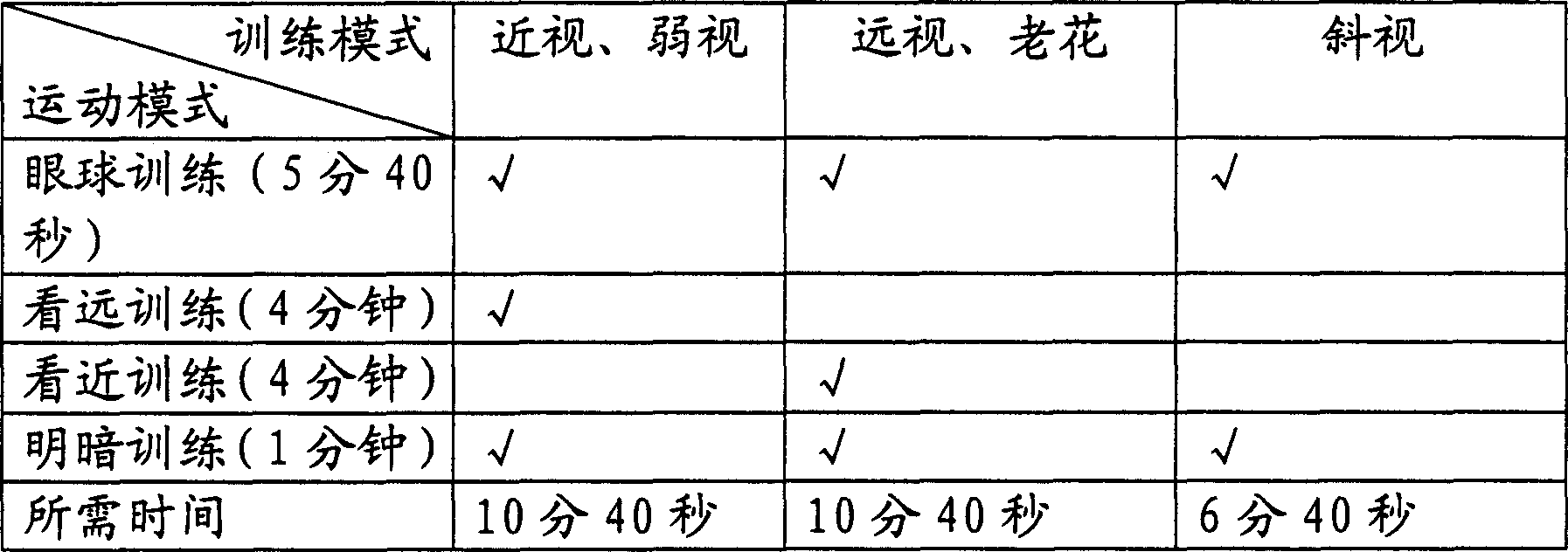
[0015] In the vision correction method of the present invention, the patient's eyes focus on the moving bright spots and images displayed on the compute...


PUM


Abstract

A method for testing the vision of a person includes such steps as displaying the vision testing image on the display screen of computer, using a controller to input the up, down, left, or right signal relative to said testing image by the person to be tested, and determining the vision level of the person if continuous two errors are inputted. A method for improving vision of a person includes such steps as displaying a moving bright dot or image on the display screen of computer and tracking the moving bright dot or image by the eyeballs of the person whose vision is going to be improved.

Description

technical field [0001] The invention relates to a vision detection and correction method. Background technique [0002] The display of the visual mark of the current vision care correcting device is in a small field of view. Usually only a few light-emitting diodes form an optotype, and each group of optotypes lights up alternately or at the same time, and then forms an optotype image through the refraction and reflection of single, double, and three-sided mirrors. Due to the small field of view, the use of this type of correction device requires minimal eye movement. , It takes a long time to correct. This type of correction device cannot fully exercise and exercise the various organs of the eye, and cannot fully improve the blood circulation of the eye organs, metabolism and strengthen the functions of various sports muscles, so it cannot fully correct myopia, strabismus, amblyopia and Presbyopia and other visual impairment invention content. The commonly used visual acu...

Claims


Application Information

Patent Timeline
Patent Type & Authority Applications(China)
IPC IPC(8): A61B3/028A61B3/032
Inventor 赵进捷
Owner 赵进捷
Learn More