Air humidifier of vehicle
A technology for air humidification and vehicle use, which is applied in air treatment equipment, vehicle parts, transportation and packaging, etc., to achieve the effect of convenient descaling, convenient disassembly and cleaning, and reducing water fluctuations
- Summary
- Abstract
- Description
- Claims
- Application Information
AI Technical Summary
Problems solved by technology
Method used
Image
Examples
Embodiment 1
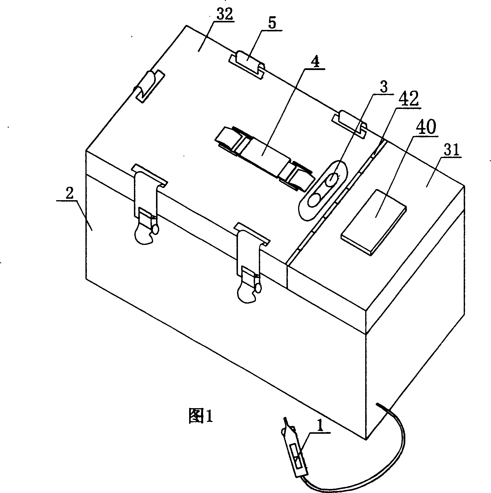
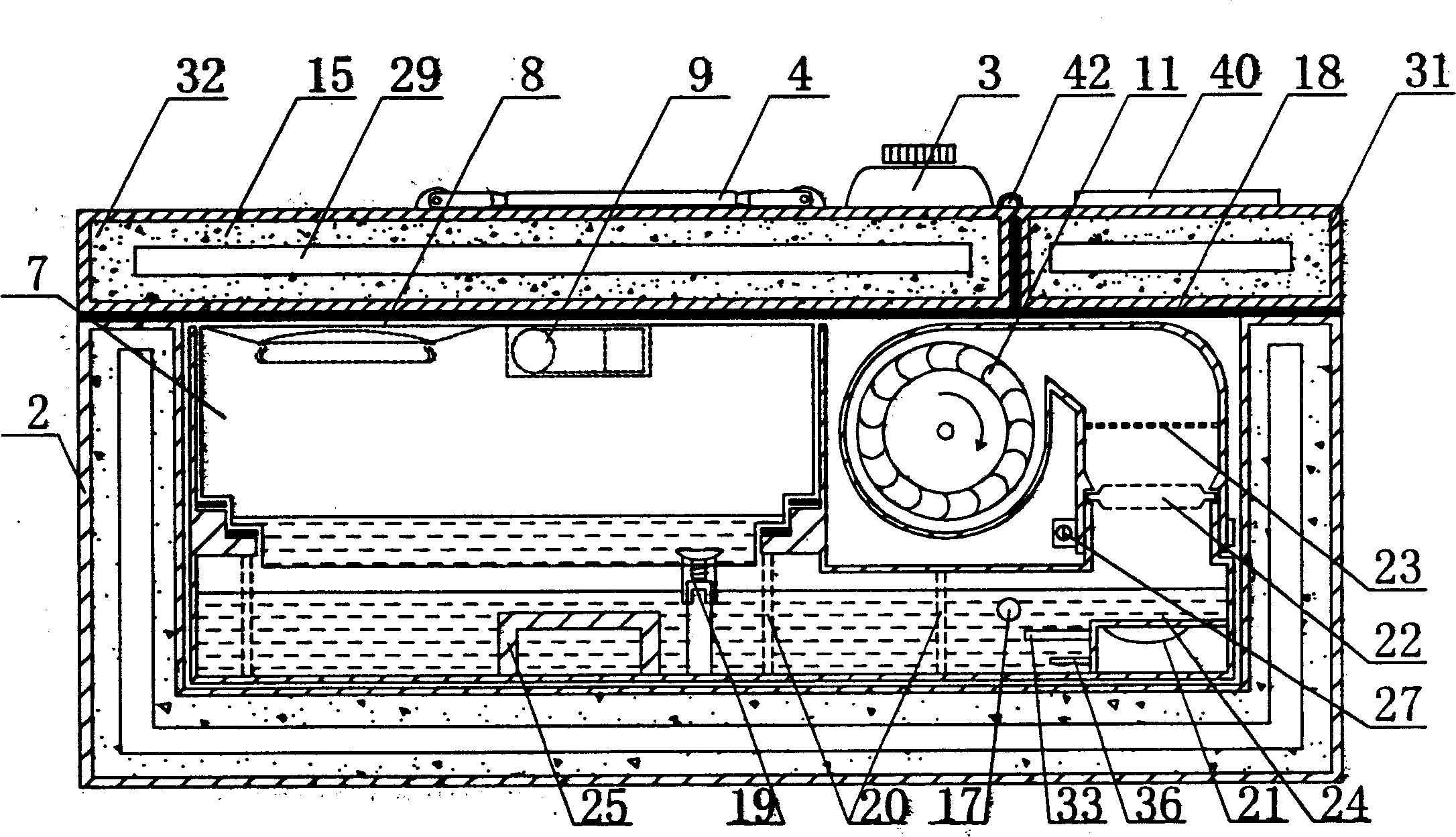
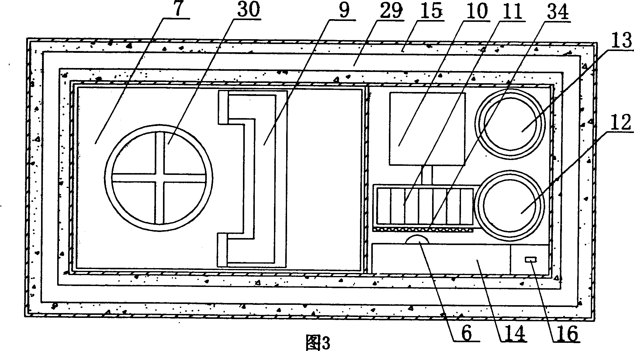
[0041] With reference to the attached drawings 1, 2, 3, 4, 5, 6, 7-1, 7-2, 8, the air humidifier for vehicle of the present invention is described in detail below.
[0042] The vehicle air humidifying device of the present invention comprises an insulated box 2, a water storage tank 7, a humidifier main body 24, a fan, an air inlet pipe 12 and an air outlet pipe 13, a water storage tank 7, a humidifier main body 24, a fan, and an air inlet pipe 12 and the air outlet pipe 13 are arranged inside the incubator 2, the humidifier main body 24 is arranged at the bottom of the incubator 2, the water storage tank 7, the air inlet pipe 12 and the air outlet pipe 13 are arranged above the humidifier main body 24, and the water storage tank 7 passes through the water tank The water switch 19 communicates with the humidifier main body 24 , the ultrasonic transducer 21 is arranged in the humidifier main body 24 , and is located below the air outlet pipe 13 , and the fan is arranged at the f...
Embodiment 2
[0053] With reference to accompanying drawings 9, 10, 11, 12, 13, 14, 15, 16, 17, 18 of the description, the vehicle air humidifier of the present invention will be described in detail below.
[0054] The incubator 2 may include a separate incubator A43 and an incubator B44. The water storage tank 7 and the humidifier main body 24 are arranged in the incubator A43, and the fan is arranged in the incubator B44. Air inlet ducts are arranged inside the two incubators. 12 and air outlet pipe 13, the air inlet pipe 12 inside the incubator A43 communicates with the air inlet pipe 12 inside the incubator B44 through the pipeline, and the air outlet pipe 13 inside the incubator A43 communicates with the air outlet pipe inside the incubator B44 through the pipeline 12 communicates, the humidifier main body 24 is arranged at the bottom of the incubator A43, the water storage tank 7, the air inlet pipe 12 and the air outlet pipe 13 are arranged above the humidifier main body 24, and the f...
PUM
 Abstract
Description
Claims
Application Information
 - R&D
- Intellectual Property
- Life Sciences
- Materials
- Tech Scout
- Unparalleled Data Quality
- Higher Quality Content
- 60% Fewer Hallucinations
Browse by: Latest US Patents, China's latest patents, Technical Efficacy Thesaurus, Application Domain, Technology Topic, Popular Technical Reports.
© 2025 PatSnap. All rights reserved.Legal|Privacy policy|Modern Slavery Act Transparency Statement|Sitemap|About US| Contact US: help@patsnap.com


