
Light quantity control device and camera device

A technology for controlling the amount of light and optical devices, used in cameras, controlling exposure, aperture, etc.

Inactive Publication Date: 2006-11-01
SONY CORP
View PDF1 Cites 10 Cited by
  • Summary
  • Abstract
  • Description
  • Claims
  • Application Information

AI Technical Summary

Problems solved by technology

These properties can only control light transmission in a part of the visible region

Method used


Image

  • Light quantity control device and camera device
  • Light quantity control device and camera device
  • Light quantity control device and camera device

Examples


Embodiment Construction

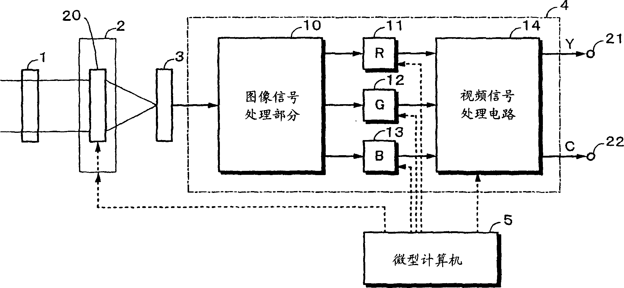
[0022] Next, embodiments of the present invention will be described with reference to the drawings. figure 1 An example of the structure of the camera device according to the embodiment of the present invention is shown. The optical device 1 is an optical filter that blocks light having a wavelength longer than a predetermined wavelength. The image optical system 2 has a lens system (not shown) and a property device 20 that controls light transmittance using liquid crystal. The property device 20 includes two opposing transparent electrodes on which a predetermined alignment process has been performed, and liquid crystal is sandwiched therebetween. When the voltage applied to the electrodes is controlled, the light transmittance can be changed from an emission state with light transmittance close to 100% to a block state with light transmittance close to 0%. The image sensor 3 is a device that converts incident light into electrical signals. An example of the image sensor 3...


PUM


Abstract

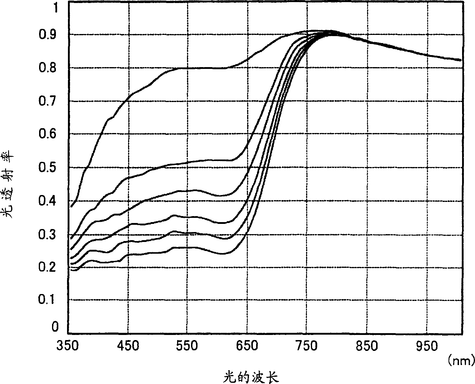
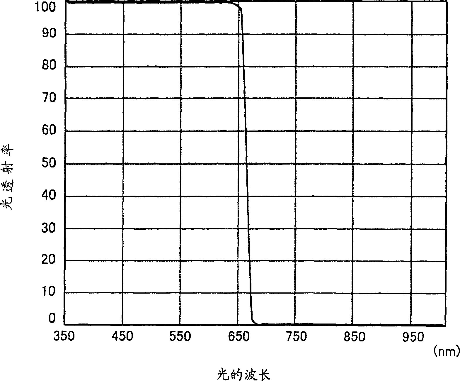
A change in tint caused by the control of the light transmittance of a physical property element is limited by a simple structure. An optical element (1) for limiting a light with at least a specified wavelength is provided to a physical element (20) such as liquid crystal capable of controlling a light transmittance. The optical element (1) limits a light on the longer wavelength side of a wavelength corresponding to a wavelength migrating from a weak-wavelength-dependent wavelength region to a strong-wavelength-dependent wavelength region in the spectral characteristics of the physical element (20). Lights from a subject have a light with at least a specified wavelength limited at the optical element (1), and have light transmittance controlled at the physical element (20) to enter an imaging element (3). Owing to the optical element (1), a light in a wavelength region where the spectral characteristics of the physical element (20) are stable is selectively allowed to enter the imaging element (3), thereby keeping nearly constant a color balance even if the light transmittance of the physical element (20) is changed.

Description

technical field [0001] The present invention relates to a light amount control device and a camera device that control the amount of light entering an image sensor that converts light into electricity using a property device capable of controlling light transmittance. Background technique [0002] As a device for controlling incident light of a camera or the like, a mechanical aperture is used. In an image optical system, light emitted from an object enters an image sensor such as a CCD (Charge Coupled Device) that converts light into electricity through an optical system. In this structure, a mechanical aperture is arranged in the optical system. The mechanical aperture controls the amount of light entering the image sensor to control the exposure of the image sensor. The mechanical diaphragm has a structure in which the aperture ratio of the diaphragm is mechanically changed to limit the amount of incident light. When a mechanical aperture is used, since the aperture ra...

Claims


Application Information

Patent Timeline
Patent Type & Authority Applications(China)
IPC IPC(8): G02F1/01G03B7/18G02B5/00G02B5/22G03B9/02G03B11/00H04N5/238
CPCG02B5/22
Inventor 佐藤裕田部井浩之仲山延孝
Owner SONY CORP
Learn More