Method for producing high voltage gas discharge lamp tube

A manufacturing method and high-pressure gas technology, applied in the manufacture of discharge tubes/lamps, gas discharge lamps, discharge lamps, etc., can solve problems such as accelerated corrosion of metal foil electrical conductors 6, production cost and efficiency problems, and difficulty in reaching

Inactive Publication Date: 2006-11-08
GLORY PRAISE PHOTRONICS CORP
View PDF1 Cites 2 Cited by
  • Summary
  • Abstract
  • Description
  • Claims
  • Application Information

AI Technical Summary

Problems solved by technology

[0004] The above-mentioned high-pressure gas discharge lamp tube 1 has ultraviolet intensifiers (external coils 45, 48) or elastic clips (not shown) around the periphery of the cavity 10, which can indeed increase the lighting effect of the lamp. However, this high-pressure gas discharge lamp The manufacturing method of the tube 1 must add additional processes for the formation of the cavity 10, resulting in additional production costs and efficiency problems, and it is difficult to achieve the same ratio of the gas in the cavity 10 and the gas in the high-pressure gas discharge lamp tube 1, Metal halides will also increase the gas concentration and accelerate the corrosion of the electrical conductor 6 in the form of metal foil. Therefore, a method for manufacturing a high-pressure gas discharge lamp that can effectively utilize the enhancement of ultraviolet rays and improve the lighting rate has become a concern. subject

Method used


Image

  • Method for producing high voltage gas discharge lamp tube
  • Method for producing high voltage gas discharge lamp tube
  • Method for producing high voltage gas discharge lamp tube

Examples


Embodiment Construction

[0022] Regarding the characteristics and practice of the present invention, the preferred embodiments are described in detail below in conjunction with the accompanying drawings.

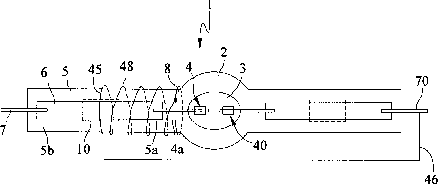
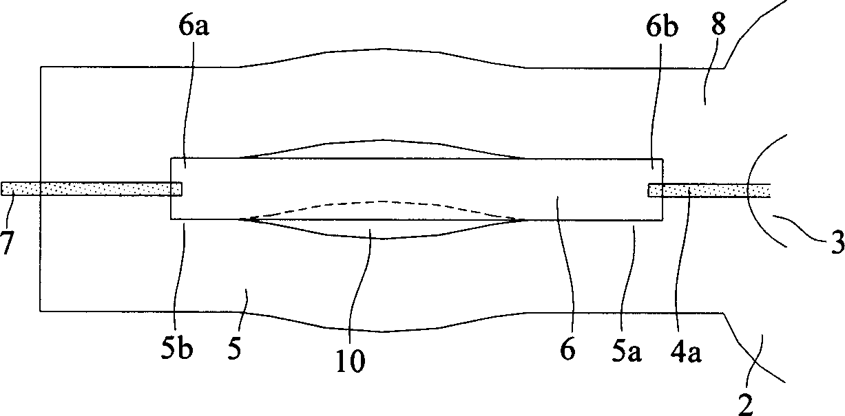
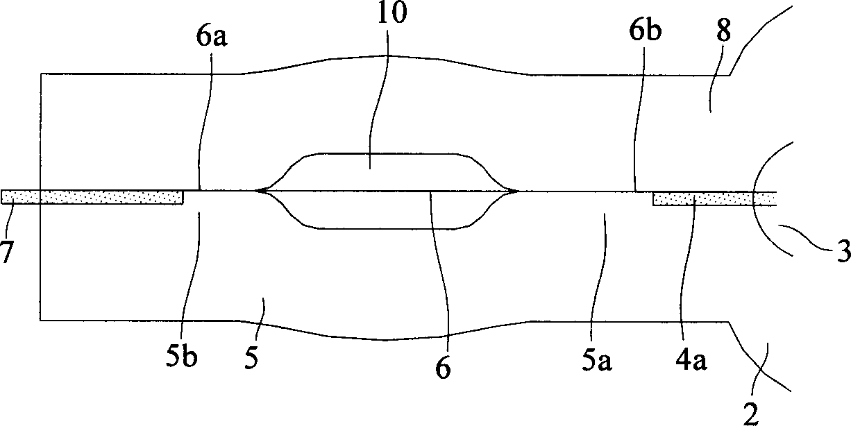
[0023] like image 3 As shown, the present invention proposes a manufacturing method of a high-pressure gas discharge lamp tube. The embodiment is that in the process of manufacturing the high-pressure gas discharge lamp tube 1, a light-emitting part 2 is sealed with the side extending on both sides of the light-emitting part 2. 5, due to the heat expansion and contraction effect of the metal foil 6, the electrode 4a, and the discharge lamp tube 1, a gap of width W is naturally formed between an adjacent metal foil 6 and a discharge space 3, and the gap is around the width The inner diameter space of the gap of the electrode 4a of d, using this naturally formed method, the gap filled with inert gas can be obtained without additional adjustment process, and because the gap communicates with the disch...


PUM


Abstract

This invention relates to a method for producing high pressure gas discharge lamp pipes, when enclosing a light emitting part and side pipes extending from both sides of the part, a clearance is formed between an adjacent foil and a discharge space and a ceramic film layer is coated on the clearance and the side pipe surface corresponding to the foil to be baked, then the surface of the clearance is covered by a metal ring or a metal coil, one end of which is connected to an exterior metal lead of the other side pipe.

Description

technical field [0001] The invention relates to a method for manufacturing an electric lamp tube, in particular to a method for manufacturing a high-pressure gas discharge lamp tube. Background technique [0002] figure 1 It is a schematic diagram of a high-pressure gas discharge lamp tube 1 in the prior art, disclosed in U.S. Patent No. 6,563,267, wherein the discharge lamp tube 1 is surrounded by a glass discharge tube 2 containing an ionizable filler (generally mercury, inert gas, metal halide) discharge space 3, which contains the first electrode 4 and the second electrode 40, and the high-pressure gas discharge lamp 1 is effectively charged and discharged due to the arc effect of the first electrode 4 and the second electrode 40 during operation. , light emission, the discharge lamp tube 1 also has a first sealing portion 5, which has a metal foil electrical conductor 6, connected to an electrode rod 4a, and connects the first electrode 4 to an external metal wire 7 ex...

Claims


Application Information

Patent Timeline
Patent Type & Authority Applications(China)
IPC IPC(8): H01J9/00H01J61/82
Inventor 吴觉宇邓克文徐俊仁陈景振
Owner GLORY PRAISE PHOTRONICS CORP
Why Eureka
Try Eureka