Method for detecting E1/T1 connection error

A connection error detection and connection technology, used in digital transmission systems, data exchange networks, electrical components, etc., can solve the problem of inability to test data to add information with specific meanings, connection errors, and inability to identify physical equipment. question

Active Publication Date: 2006-11-08
SHANGHAI HUAWEI TECH CO LTD
View PDF0 Cites 17 Cited by
  • Summary
  • Abstract
  • Description
  • Claims
  • Application Information

AI Technical Summary

Problems solved by technology

[0006] In practical applications, the above scheme has the following problems: when the physical connection is wrong and it is not a loopback connection, but a mandarin duck connection, it cannot be detected by sending a pseudo-random code on the physical link
In other words, this detection method can only realize the loopback detection of E1 / T1, and cannot realize the detection of mandarin duck lines.
In addition, the loopback detection must be done offline, the test data and normal business data cannot be sent in parallel, and it is impossible to obtain whether the E1 / T1 is in the loopback state in real time
[0007] The main reason for this situation is that the test data is independently generated by the physical layer chip, so the content of the test data cannot be controlled, and it is impossible to add information with specific meanings to the test data.
Therefore, it can only recognize the pseudo-random code sent by itself, but not the pseudo-random code sent by other links
like figure 1 As shown, when the physical device is connected by a mandarin duck line, even if link 2 receives the pseudo-random code sent by link 1 for testing, it will receive the pseudo-random code as normal data, so it cannot identify the physical device. Whether there is a connection error of the mandarin duck line in the device
In addition, due to the limitation of the chip, sending the pseudo-random code needs to occupy all the E1 / T1 time slots. Therefore, the loopback detection must be offline, and it is impossible to obtain whether the E1 / T1 is in the loopback state in real time.

Method used


Image

  • Method for detecting E1/T1 connection error
  • Method for detecting E1/T1 connection error
  • Method for detecting E1/T1 connection error

Examples


Embodiment Construction

[0036] In order to make the purpose, technical solution and advantages of the present invention clearer, the present invention will be further described in detail below in conjunction with the accompanying drawings.

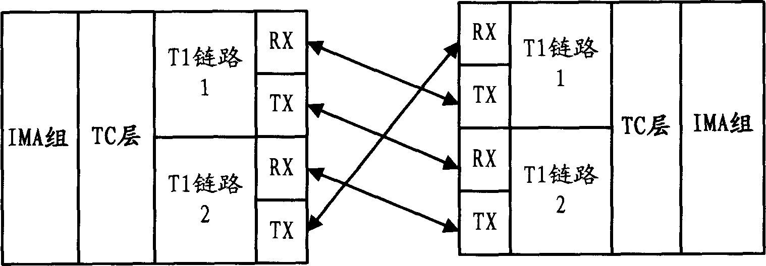
[0037] In the first embodiment of the present invention, when two communication devices are directly connected in T1 mode (such as image 3 shown), can be based on Figure 4 The flow chart of the method is shown to detect whether there is a physical connection error in the T1 link. The steps of this process are described in detail below.

[0038] Such as Figure 4 As shown, in step 410, the high-level data link control protocol controller (HDLC controller) sends and receives test signals to the T1 physical link at "FDL Bits". "FDL Bits" are reserved bits in the ESF frame in T1 mode. In the ESF frame, there are 24 control bits, of which 12 control bits (1, 3, 5, 7, 9, 11, 13, 15, 17, 19, 21) are reserved for data link communication at the sending and receiving...


PUM


Abstract

The present invention discloses a method for detecting E1 / T1 connection error. In the present invention, HDLC controller utilizes idleness or according to protocol reserved bit transmitting / receiving test signal, if capable of receiving local side sent test signal then judging occurring loop back connection. When Two equipment straight connected in E1 / T1 or intermediate equipment using transparent transmission to E1 / T1 frame structure information, capable of using FDL bits in T1 ESF frame or idleness bit Sa bits in E1 PCM frame 0 time slot NFAS signal to transmit test signal. In intermediate equipment without E1 / T1frame structure frame structure signal transparent transmission function, idleness time slot or its combination can be used for transmitting said test signal. Test signal can identify each E / T physical link, for example capable of according to link index number encoding generation; if receiving other link test signal then judging occurring mandarin duck line connection (one line contacting earth, one line contacting battery).

Description

technical field [0001] The present invention relates to E1 / T1 technology, in particular to E1 / T1 connection error detection technology. Background technique [0002] At present, in the Iub interface between the 3G base station and the base station controller, the E1 / T1 mode is often used for connection. E1 is the bandwidth rate standard of the primary group (or Kam group) of the pulse code modulation multiplexing system digital system in Europe. It includes 32 channels of 64kbit / s, and the bandwidth rate of the primary group is 2.048Mbit / s. my country also adopts this standard. The frame length of an E1 is 256 bits, divided into 32 time slots, each time slot is 8 bits. There are 8k E1 frames passing through the interface per second, that is, 8K*256=2048kbps. Each time slot occupies 8 bits in the E1 frame, 8*8k=64k, that is, one E1 contains 32 64K. E1 has three modes: framing, multi-frame and non-framing. In the framed E1, the 0th time slot is used to transmit frame synch...

Claims


Application Information

Patent Timeline
IPC IPC(8): H04L12/26
Inventor 徐炜曹少文
Owner SHANGHAI HUAWEI TECH CO LTD
Why Eureka
Try Eureka