

Component mounting method and apparatus
An installation method and component technology, applied in the direction of electrical components, electrical components, etc., can solve the problems of inaccessibility and high installation accuracy
- Summary
- Abstract
- Description
- Claims
- Application Information
AI Technical Summary
Problems solved by technology
Method used
Image

Examples
no. 1 example
[0115] A first embodiment according to the present invention will be described in detail below with reference to the drawings.
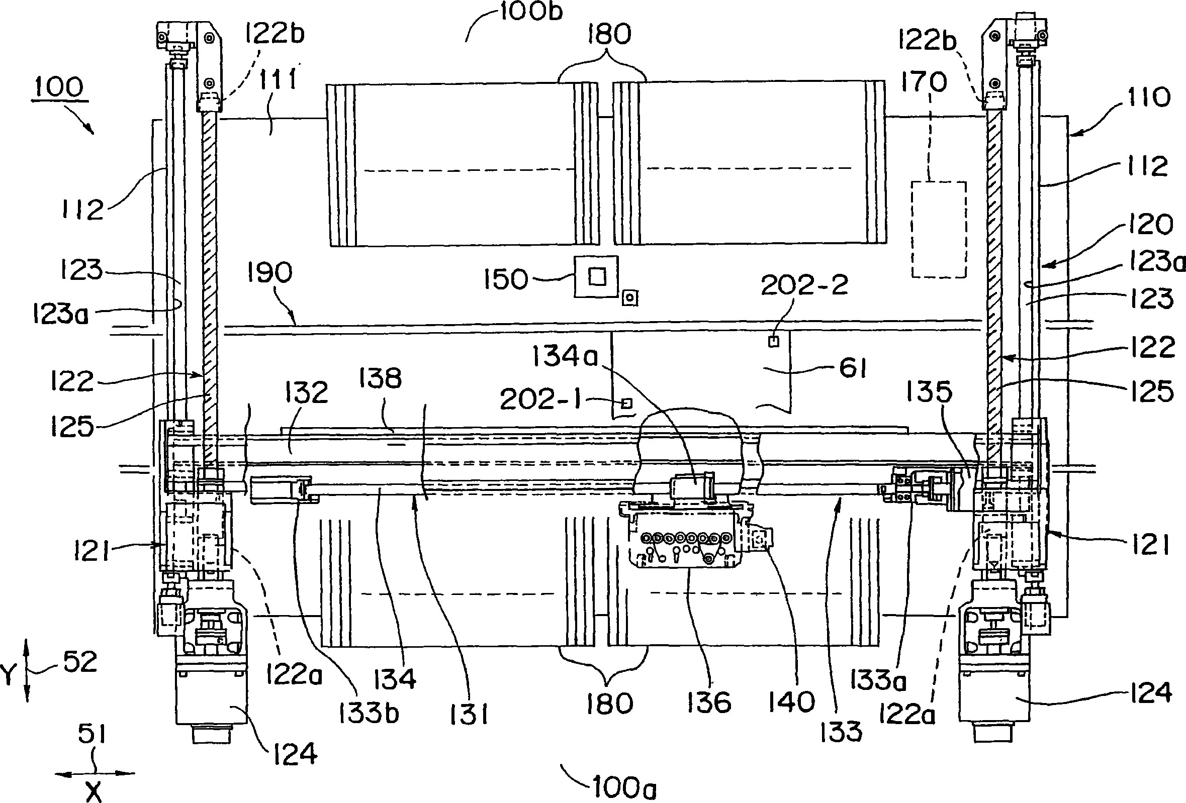
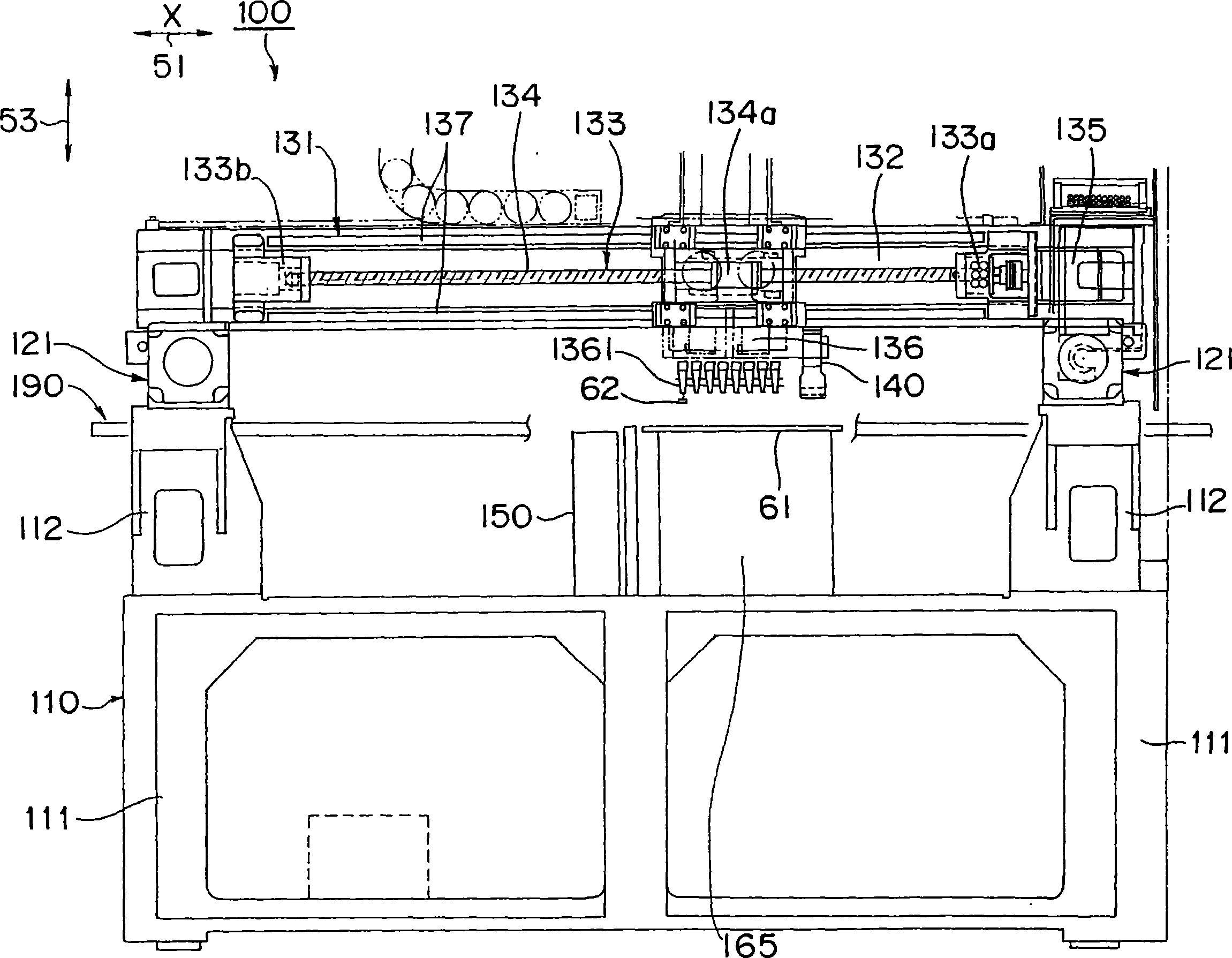
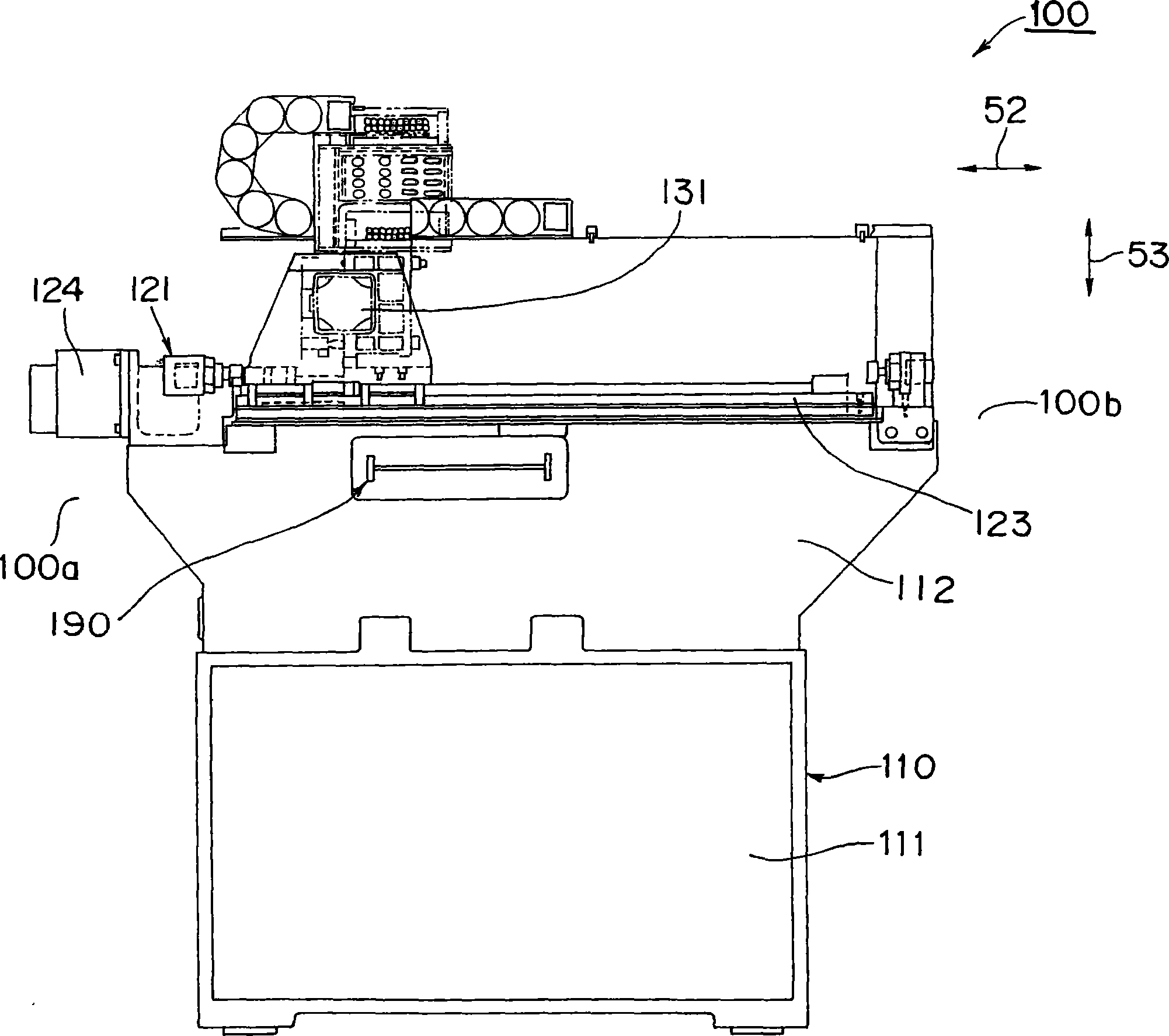
[0116] Such as Figures 1 to 4 As shown in , the component mounting apparatus 100 capable of implementing the component mounting method according to the first embodiment includes a chassis 110 as a basic structural element, an X-Y robot 120, a board recognition camera 140 as an example of a board recognition device for recognizing a board recognition target , a component recognition camera 150 , a control unit 170 , a component feeding unit 180 , and a board conveying unit 190 .
[0117]The chassis 110 is mounted thereon the X-Y robot 120, the component recognition camera 150, the control unit 170, the component feeding unit 180, and the board delivery unit 190, and is constituted by a rectangular parallelepiped base portion 111 and a Y-axis robot leg portion 112 base. The base portion 111 and the Y-axis robot leg 112, that is, the chassis 110, are...
PUM
 Abstract
Description
Claims
Application Information