
Safety cylinder of injector

A technology for safe injection and syringes, applied in the direction of syringes, hypodermic injection devices, infusion sets, etc., can solve the problems of danger, retraction and entry into the cylinder body 60, and insufficient tightness to avoid protruding or shrinking input effect

Inactive Publication Date: 2006-11-15
汪贤宗
View PDF0 Cites 10 Cited by
  • Summary
  • Abstract
  • Description
  • Claims
  • Application Information

AI Technical Summary

Problems solved by technology

[0006] But the design of the above-mentioned commonly used safety injection syringe, although its conception is good, but there are some shortcomings in use, mainly because there is only a single anti-leakage ring 71 between the plunger 70 and the cylinder body 60. In this design, when the needle 73 at the other end of the plunger 70 is inserted into hard skin or blood vessels, the needle 73 and the plunger 70 will often retreat and enter the barrel 60. or before injecting the liquid medicine, when the pushing strength of the medical staff is too large or too fast when testing the liquid medicine, the plunger 70 will be pushed by the hydraulic pressure and drive the needle 73 to protrude forward and separate from the cylinder 60 , resulting in great danger during injection; if more than two designs are added to the anti-leakage ring 71 in order to solve this problem, the engagement force between the engaging groove 820 and the retaining column 72 will appear after the injection is completed. , it is not enough to overcome the tightness of the two anti-leakage rings 71 on the plunger 70, so that the plunger 70 and the needle 73 cannot be pulled back into the barrel 60, so that the commonly used safety injection syringes appear in this design. Dilemma of technical bottleneck situation, this technical difficulty has been unresolved for a long time

Method used


Image

  • Safety cylinder of injector
  • Safety cylinder of injector
  • Safety cylinder of injector

Examples


Embodiment Construction

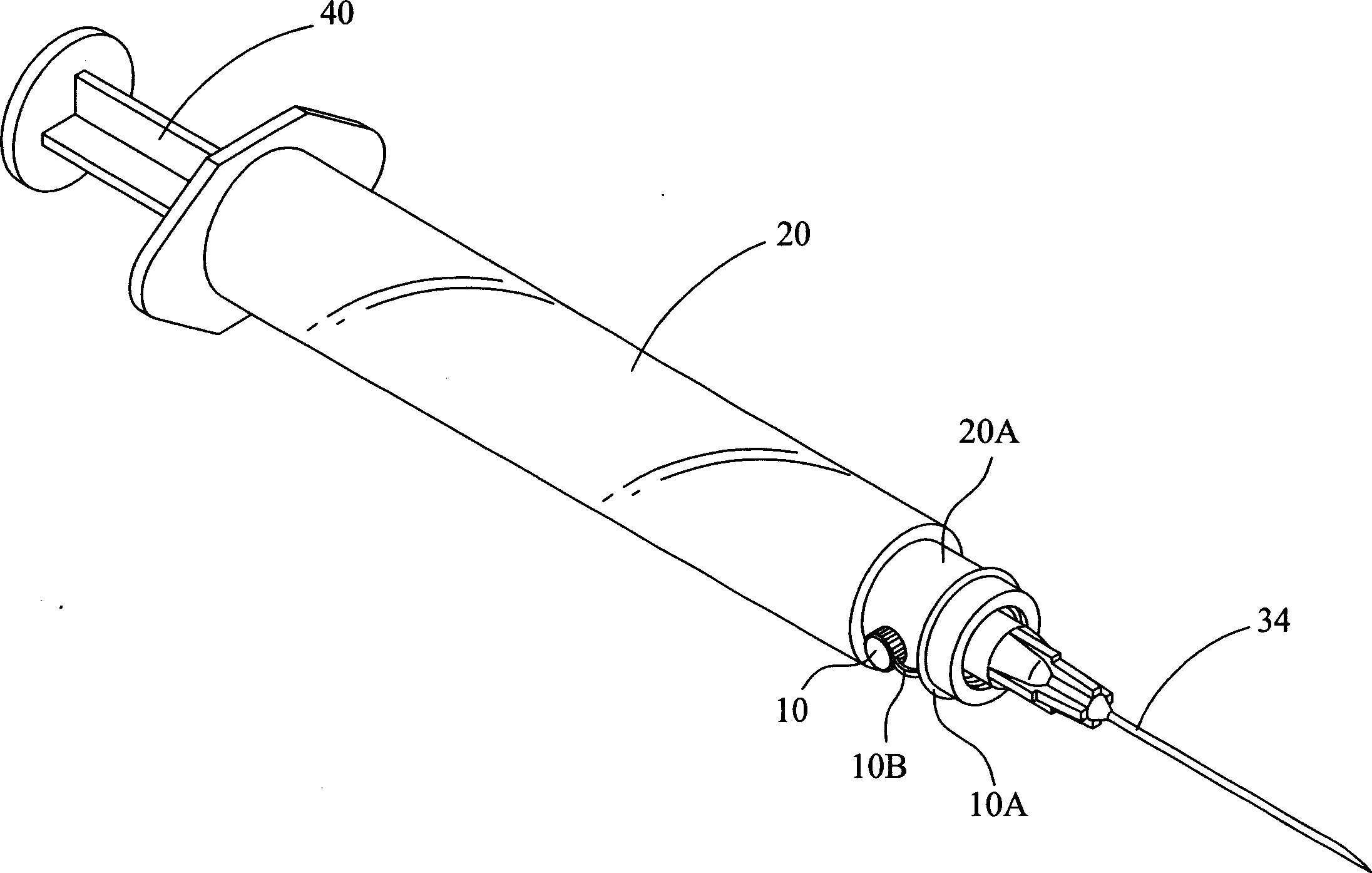
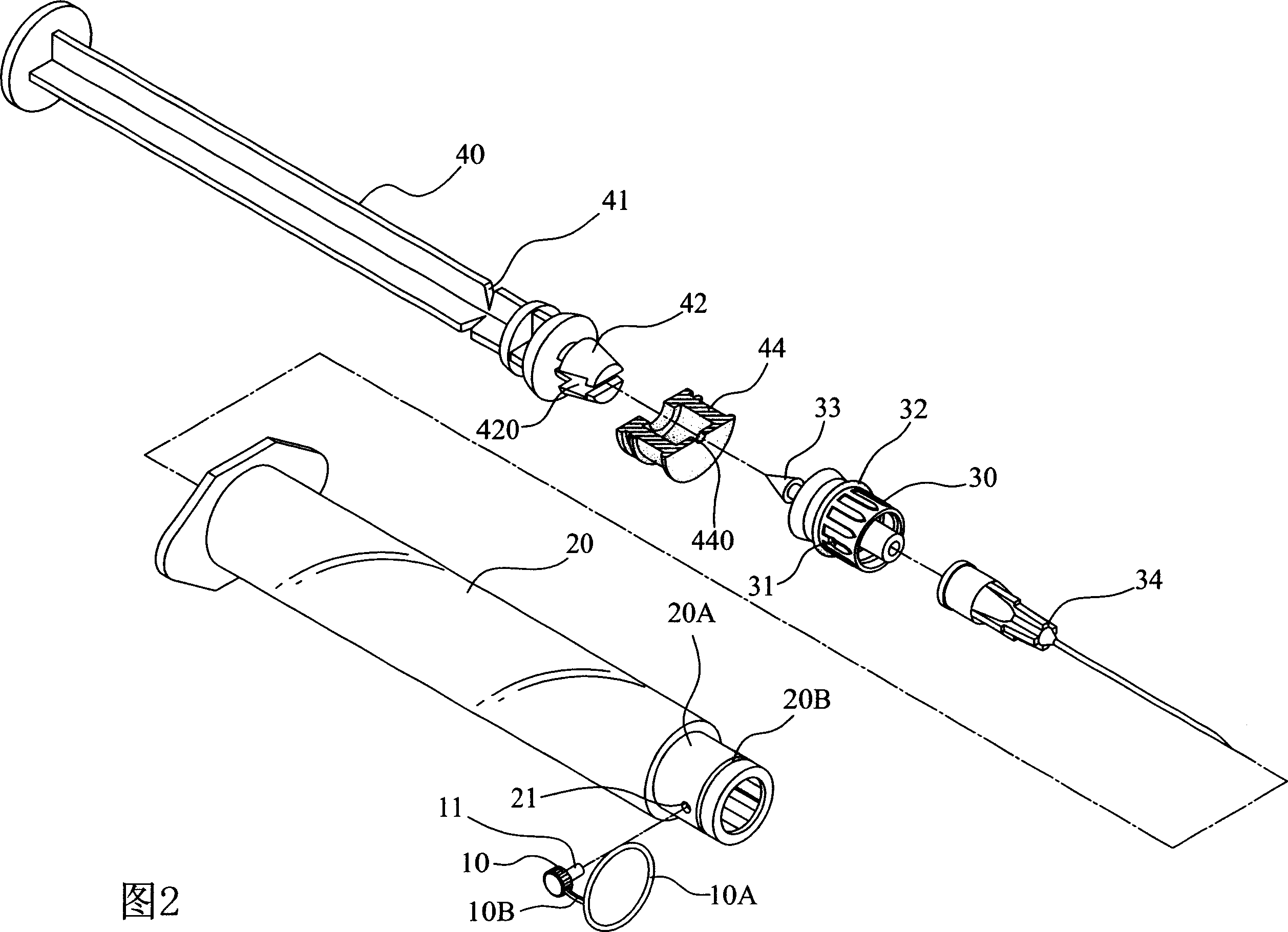
[0026] See first figure 1 , Figure 2 and image 3 As shown, it is a perspective view of a preferred embodiment of the present invention, a perspective exploded view and a schematic sectional view. The present invention is mainly provided with a hollow and elongated cylinder 20, and the front end of the cylinder 20 can accommodate a plunger 30. Set, and make the cylindrical body 20 opposite to the peripheral side of the end where the plunger 30 can be embedded, then a perforation 21 (as shown in Figure 2 ) is perforated, and the plunger 30 is embedded in the cylindrical body 20. At the position of the perforation 21, a positioning hole 31 corresponding to the size of the perforation is provided, and the outer side of the perforation 21 of the cylinder 20 is provided with a bolt positioning member with a connecting unit 10A socketed with the front end 20A of the cylinder 20 10. The positioning member 10 can be a positioning bolt with one end slightly larger than the positionin...


PUM


Abstract

A high-safety injector features that a locator at the front end of injecting tube is sleeved by a connection unit and the connection unit is embedded between injecting tube and plunger. As a result, the needle can not be moved by plunger on injecting.

Description

technical field [0001] The invention relates to a safety injection syringe, in particular to a disposable safety injection syringe which is more convenient and safe to use. Background technique [0002] According to the current safe injection syringe products, such as Figure 8 to Figure 10 As shown, it is mainly provided with a hollow and elongated cylinder 60, the front end of the cylinder 60 can be embedded with a plunger 70, and the periphery of the plunger 70 is provided with a leak-proof ring 71, so that the cylinder When the plug 70 is embedded in the front end of the cylinder 60, it can achieve watertight sealing, and the plunger 70 is embedded in the end surface of the cylinder 60, protruding toward the inside of the cylinder 60 to form an inverted cone-shaped clamping post 72, and The front end of the plunger 70 can be socketed with a needle 73; [0003] And the rear end of the cylindrical body 60 can be used to embed a push rod 80 with a breaking groove 81 in the...

Claims


Application Information

Patent Timeline
IPC IPC(8): A61M5/315A61M5/31
Inventor 汪贤宗
Owner 汪贤宗
Learn More