Interfacial boost type spinning-nozzle free electrofluid dynamic method, and its application
A non-spinneret, power-assisted technology, which is applied in the field of new electrohydrodynamics, can solve the problems of no spinneret and achieve the effect of promoting application
- Summary
- Abstract
- Description
- Claims
- Application Information
AI Technical Summary
Problems solved by technology
Method used
Image
Examples
Embodiment 1
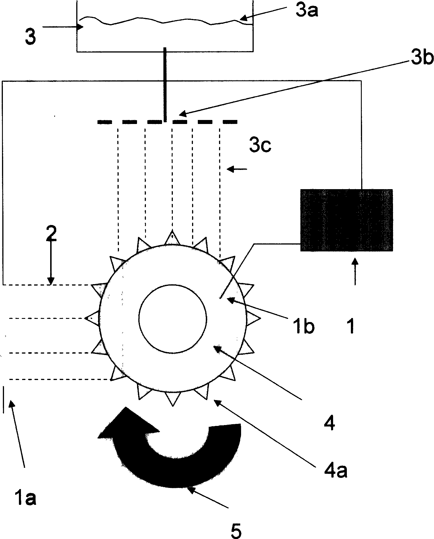
[0043] The electrohydrodynamic method of the centrifugal force type electrohydrodynamic method of spraying the material to be processed without a spinneret such as figure 1 shown. The processed material is sprayed onto the roller 4 through the processed material shower assembly 3b, and when the roller rotates, the showered processed material 3c is subjected to centrifugal force through the sharp protrusion 4a on the edge of the roller. The roller was connected to a high-voltage power source 1 as the working electrode 1b, and the counter electrode was combined with the collection device 1a. When a high-voltage electric field is applied and the roller rotates, the material 3 to be processed is simultaneously subjected to centrifugal force and electrostatic force to form an electric jet 2, thereby processing the material to be processed.
Embodiment 2
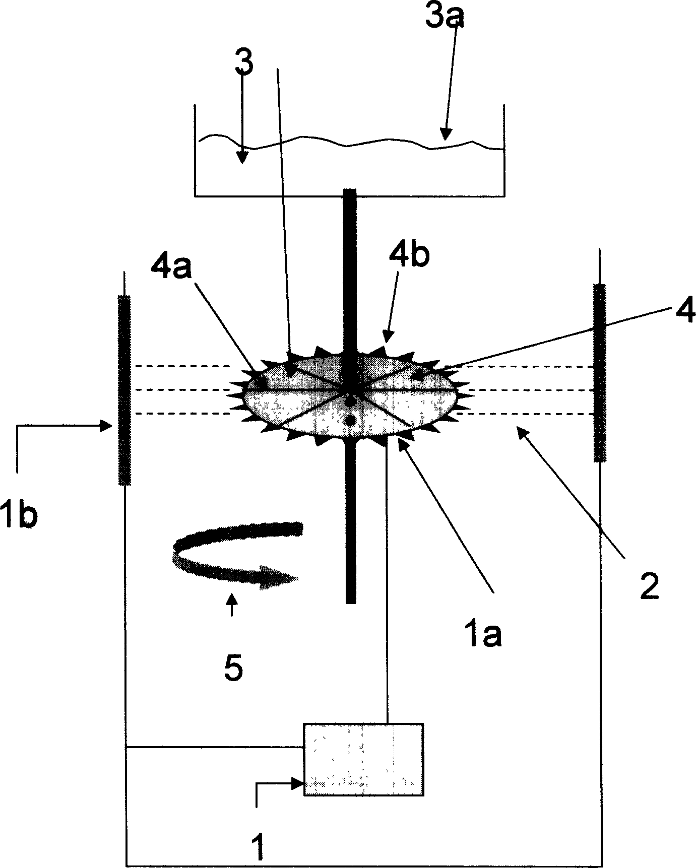
[0045] The system structure of spinnerless rotary disc centrifugal electrohydrodynamic method is as follows: figure 2 shown. The material to be processed 3 is guided to the turntable 4, and when the turntable rotates, the material to be processed goes along the guide groove 4a on the turntable to the sharp protrusion 4b on the edge of the turntable to obtain centrifugal force. Connect the turntable to a high-voltage power source 1 as the working electrode 1b, and the counter electrode is combined with the collection device 1a. When a high-voltage electric field is applied and the turntable rotates, the material 3 to be processed is simultaneously subjected to centrifugal force and electrostatic force to form an electric jet 2, thereby processing the material to be processed.
Embodiment 3
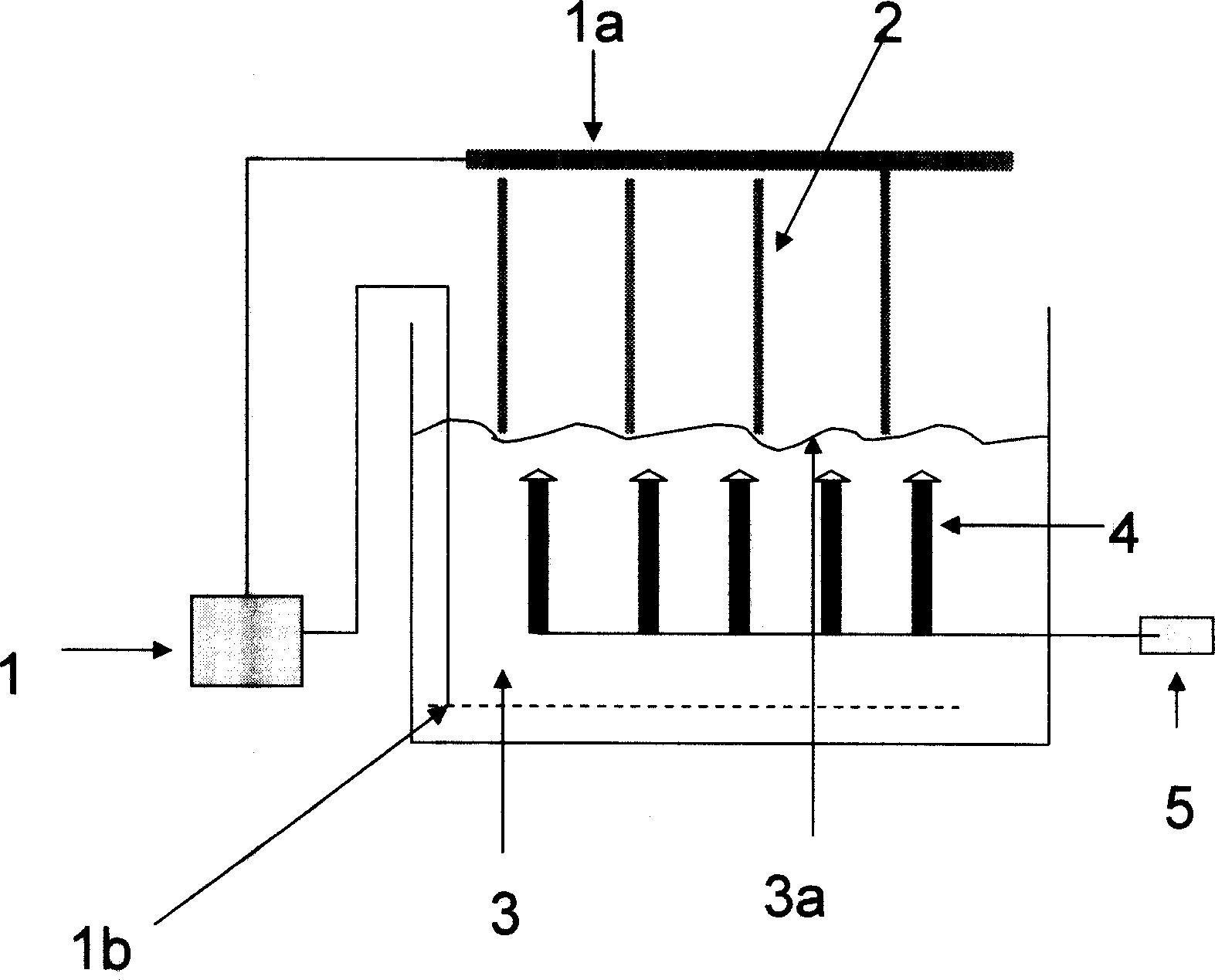
[0047] The structure of the electrohydrodynamic method system with built-in mechanical oscillation without spinneret is as follows: image 3 shown. Place the mechanical oscillating assembly 4 in the processed material 3. When the mechanical oscillating power supply 5 is turned on, the mechanical oscillating assembly vibrates and causes the processed material to oscillate. The oscillating force can cause part of the solution interface to form a sharp jet state, so it can As a boost to electrohydrodynamic methods. The high-voltage power supply 1 is connected to the working electrode 1b and placed under the liquid surface 3a of the processed material, and the counter electrode is combined with the collecting device 1a. When the mechanical oscillating power supply and the high-voltage power supply are turned on at the same time, the electrostatic force and the oscillating force act together to form an electric jet 2 and then process the processed material.
PUM
 Abstract
Description
Claims
Application Information
 - R&D
- Intellectual Property
- Life Sciences
- Materials
- Tech Scout
- Unparalleled Data Quality
- Higher Quality Content
- 60% Fewer Hallucinations
Browse by: Latest US Patents, China's latest patents, Technical Efficacy Thesaurus, Application Domain, Technology Topic, Popular Technical Reports.
© 2025 PatSnap. All rights reserved.Legal|Privacy policy|Modern Slavery Act Transparency Statement|Sitemap|About US| Contact US: help@patsnap.com


