

Wire rod straightener for wire hook formation machine
A forming machine and wire technology, applied in the field of machinery, can solve the problems of poor straightening effect, high processing cost, low production efficiency, etc., and achieve the effects of simple structure, high work efficiency and smooth conveying.
- Summary
- Abstract
- Description
- Claims
- Application Information
AI Technical Summary
Problems solved by technology
Method used
Image

Examples
Embodiment Construction
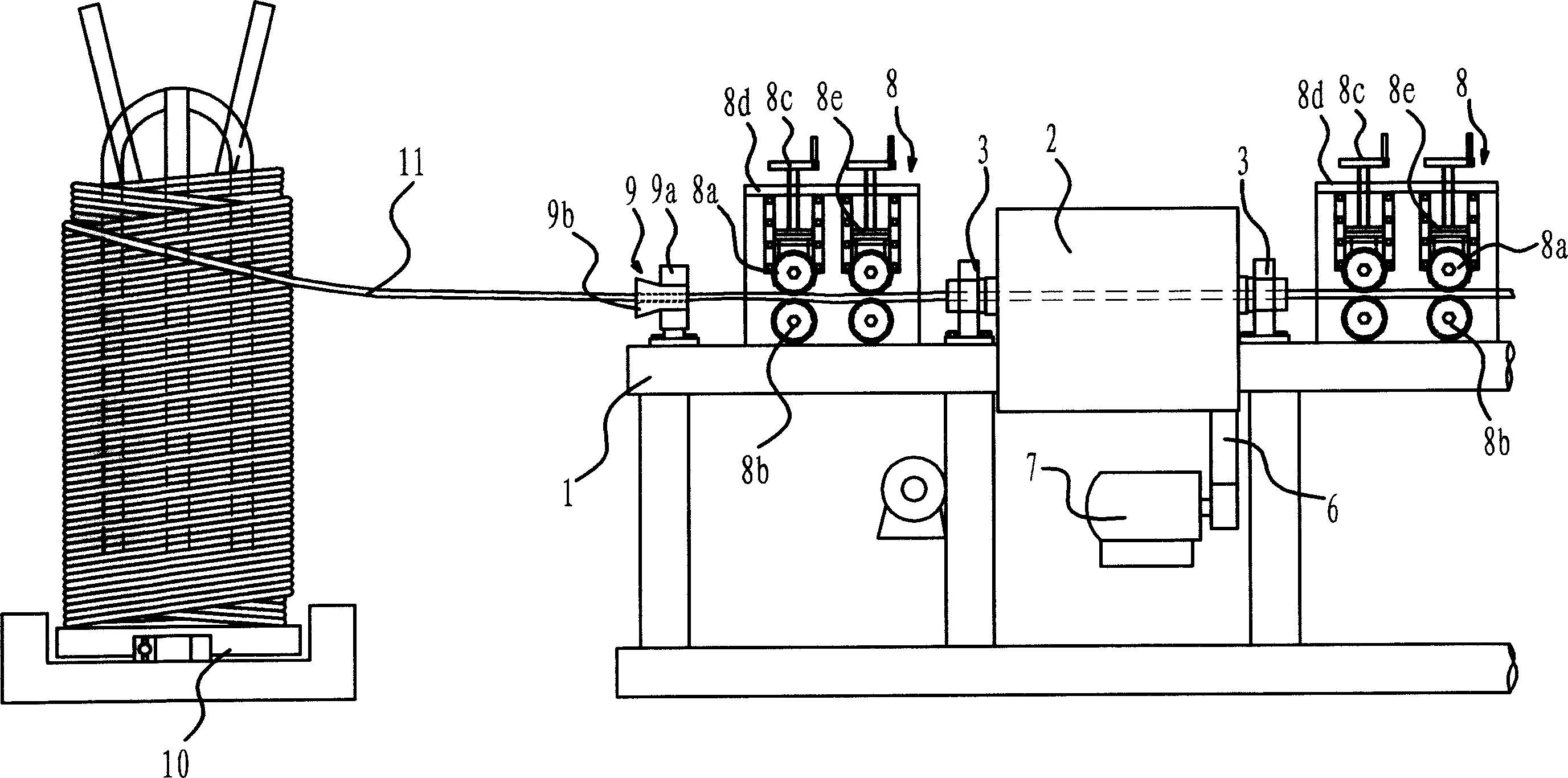
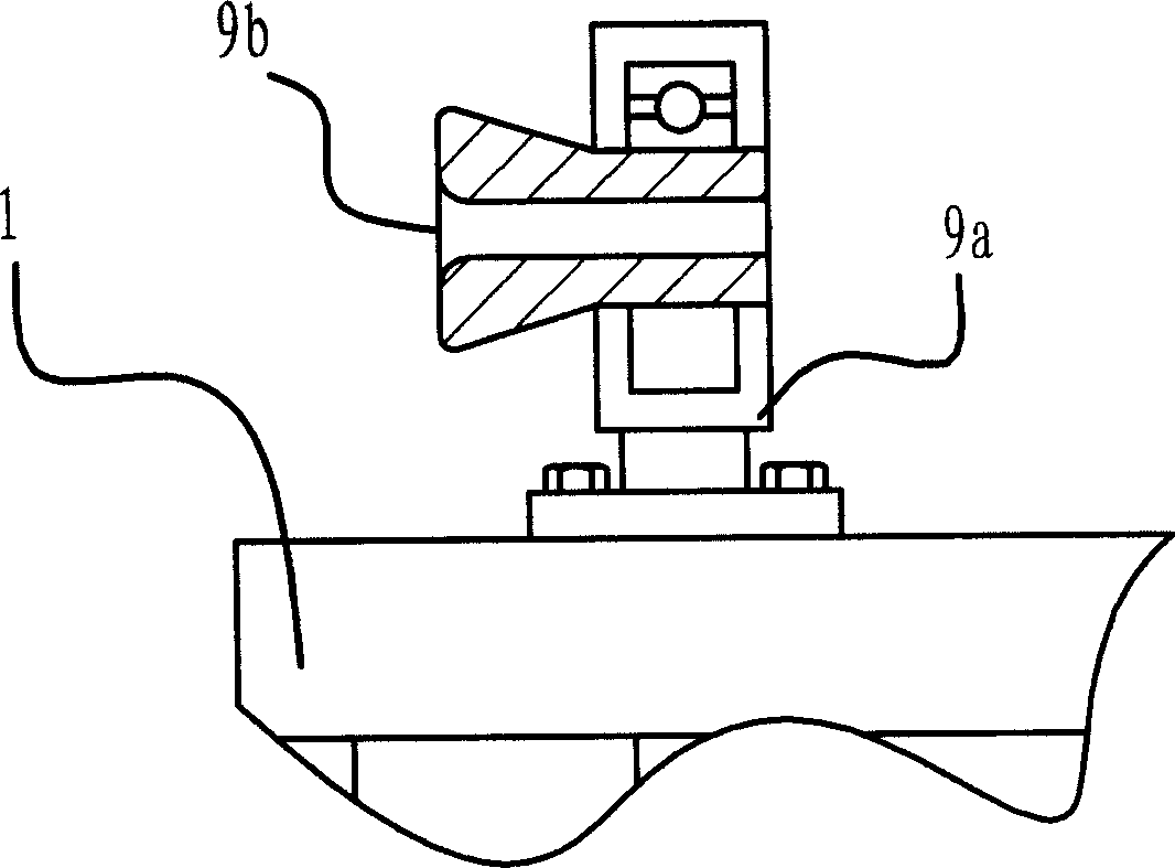
[0021] Such as figure 1 As shown, the wire straightening mechanism of the wire hook forming machine is arranged on the frame 1 of the wire hook forming machine. It includes rotary cylinder 2, straightening block 4, feeding mechanism 8, guide mechanism 9 and other components. The wire 11 is coiled on the turntable 10, and passes through a guide mechanism 9, a feeding mechanism 8, a rotary cylinder 2, and another feeding mechanism 8 in order to be straightened and transported.
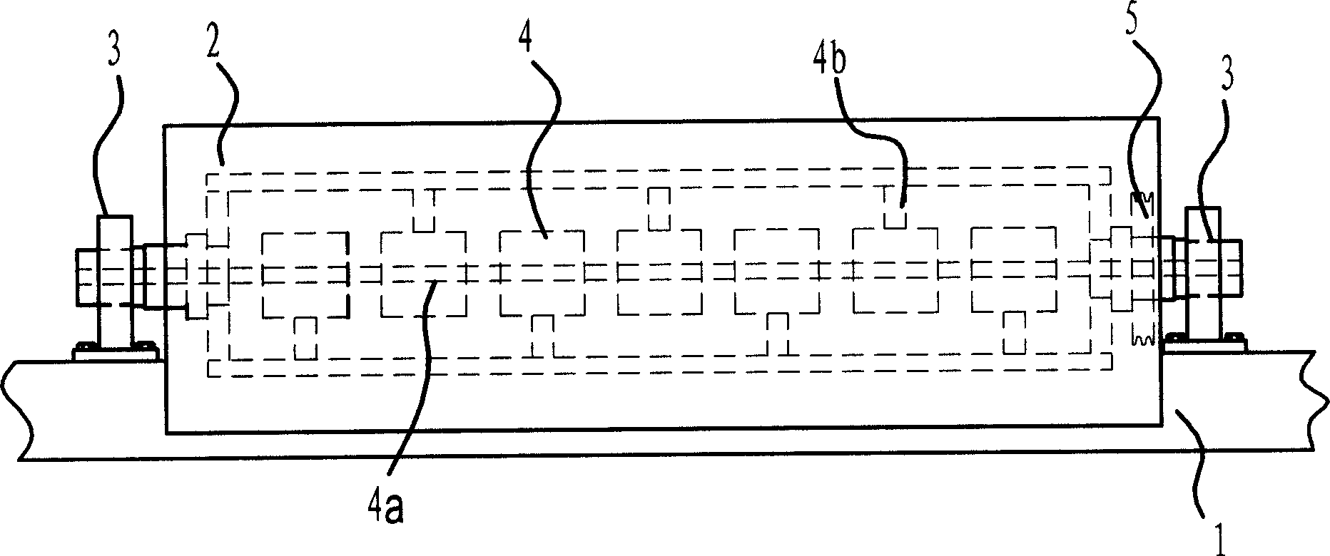
[0022] Such as figure 2 As shown, the rotary drum 2 is arranged on two bearing seats 3, and the two ends of the rotary drum 2 are respectively connected with the bearing seats 3 through a bearing. One end of the rotary drum 2 is fixed with a belt pulley 5, and the belt pulley 5 is connected with a driving motor 7 through a transmission belt 6. Driven by the driving motor 7, the rotary cylinder 2 can be driven to rotate.
[0023] Seven straightening blocks 4 which are distributed in a staggered mann...
PUM
 Abstract
Description
Claims
Application Information