Plate shape lock with high insured trirow bullet and fitted insurance comb and key thereof

A technology of marbles and keys, which is applied to flat key locks and keys with high-security three-row marbles and safety combs, and in the field of hardware lock manufacturing, which can solve problems such as inconvenient

Inactive Publication Date: 2006-11-15
陈志和
View PDF2 Cites 12 Cited by
  • Summary
  • Abstract
  • Description
  • Claims
  • Application Information

AI Technical Summary

Problems solved by technology

But the pinholes in the lock head are all on one side, and the key can only be inserted in one direction to unlock, which is not convenient enough

Method used


Image

  • Plate shape lock with high insured trirow bullet and fitted insurance comb and key thereof
  • Plate shape lock with high insured trirow bullet and fitted insurance comb and key thereof
  • Plate shape lock with high insured trirow bullet and fitted insurance comb and key thereof

Examples


Embodiment Construction

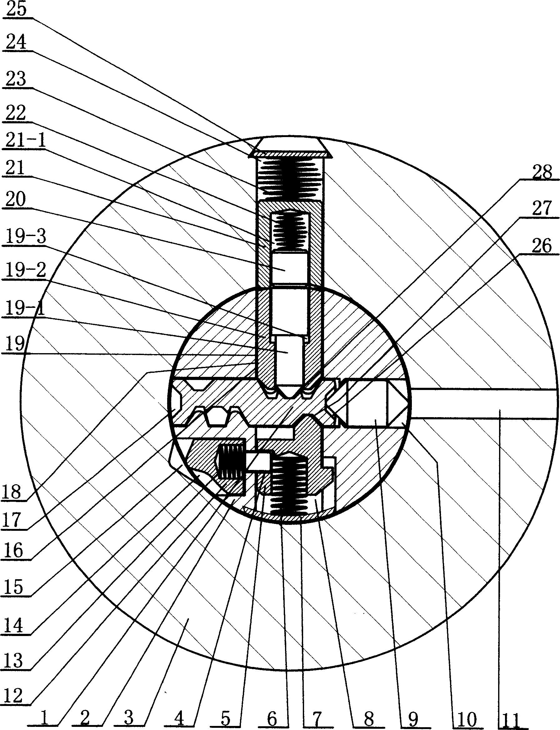
[0029] attached Figure 22 It is the first structural implementation of the present invention. Each component of the present invention is manufactured according to the accompanying drawings, and then assembled into the present invention. When the present invention is in the locked state, the safety comb 12 corresponds to the safety comb tapered groove 15, and under the promotion of the safety comb spring 13, the safety comb 12 retreats from the lock cylinder 2, and its triangular tapered tail end enters The safety comb tapered groove 15 of the lock head 3 makes the safety comb pin 12-1 originally plugged into the safety comb pin insertion hole 4 on the side of the eccentric flange pin 5 all retreat; The various eccentric flange pins 5 of 8 make the eccentric flange pins 5 all translate into the key slot 17 due to the driving force of each small spring 6 behind it. Equally, the tapered bullet 19-1 and the female marble 19-2 above the key groove 17 all can enter in the key gro...


PUM


Abstract

The present invention relates to a high-safety plate lock with three rows of balls and matched safety comb and its key. It is characterized by that on three directions in the lock core are mounted a row of eccentric flanged balls, a row of side balls and a row of selective balls, specially, on the row of eccentric flanged balls a matched safety comb is connected so as to raise its safety property. Said invention also provides the concrete structure and component composition of said plate lock.

Description

【Technical field】 [0001] The invention is a hardware lock, which is used for assembling automobiles, motorcycles, safes, safes and households and other high-insurance places to match locks, in particular to a high-insurance flat key lock with three rows of pins and safety combs and Keys belong to the hardware lock manufacturing industry. 【Background technique】 [0002] Mr. Chen Zhihe, a patent applicant in Zhongshan City, Guangdong Province, applied for a utility model patent on December 10, 2004, named "a high-security three-row key lock and key", and the patent number is 200420102222.6. The lock head has reasonable design, convenient manufacture, large amount of keys, anti-theft, anti-prying, and good safety performance. But the marble holes in this lock head are all on one side, and the key can only be inserted in one direction to unlock, which is not convenient enough. Therefore, after improving the utility model patent, a new application was filed on March 16, 2006, t...

Claims


Application Information

Patent Timeline
Patent Type & Authority Applications(China)
IPC IPC(8): E05B27/06
Inventor 陈志和陈国强
Owner 陈志和
Why Eureka
Try Eureka