
High performance internal combustion engine

An internal combustion engine, high-performance technology, applied in the direction of valve details, valve driving devices, etc., can solve problems such as insufficient inflation, low speed, intake and exhaust cam profile plumpness coefficient decline, etc.

Inactive Publication Date: 2006-11-15
晏家全
View PDF1 Cites 4 Cited by
  • Summary
  • Abstract
  • Description
  • Claims
  • Application Information

AI Technical Summary

Problems solved by technology

Since the intake pipe, cylinder and exhaust pipe are connected to each other during valve overlap, when the internal combustion engine is running at a low load or the pressure in the intake pipe is very low, exhaust gas backflow may occur, reducing the intake air volume and affecting combustion conditions
[0003] Chinese patent specification ZL01206249.9 discloses an internal combustion engine with a valve overlap angle set to 0°. This internal combustion engine is an improvement aimed at preventing the backflow of exhaust gas. In the valve timing of this internal combustion engine, the early opening angle of the intake valve and the exhaust valve delay angle are set to 0°, and the intake and exhaust valves are closed at the top dead center at the same time, so the internal combustion engine ensures good low-speed performance. However, due to the shortened intake and exhaust time of the internal combustion engine, the cam The working section of the profile is shortened accordingly, which reduces the fullness coefficient of the intake and exhaust cam profiles and reduces the valve opening time-section, especially at high speeds, insufficient inflation and unclean exhaust will occur

Method used


Image

  • High performance internal combustion engine
  • High performance internal combustion engine
  • High performance internal combustion engine

Examples


Embodiment Construction

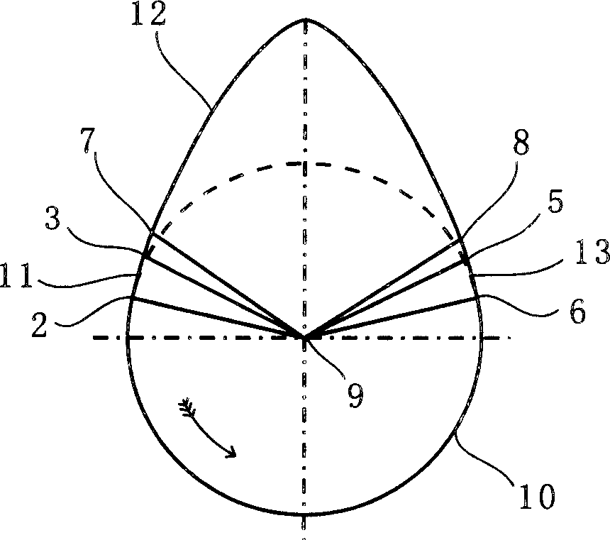
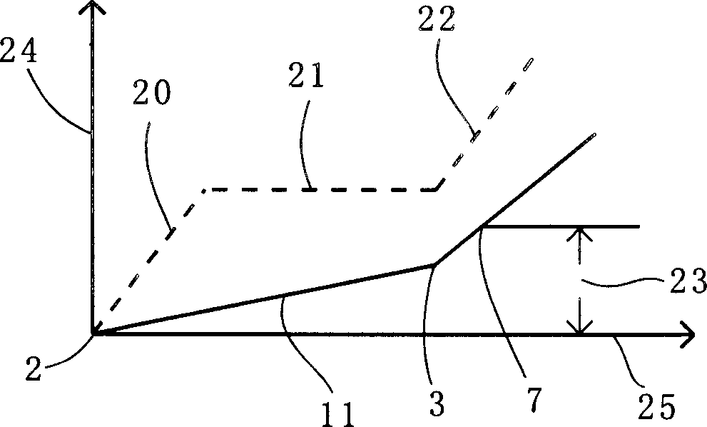
[0016] figure 1 It shows the schematic diagram of intake and exhaust cam profiles on the internal combustion engine camshaft of the present invention, point 9 in the figure is the center of the cam shaft, point 7 is to eliminate the valve clearance, point 8 is the beginning of the valve clearance, and points 6-2 are the base of the cam Circle 10, point 2-point 3 is the valve opening buffer section 11, point 3-point 5 is the working section 12, and point 5-point 6 is the valve closing buffer section 13. The figure shows that the end point 3 of its valve opening buffer section 11 is located before the valve clearance point 7 is eliminated in the cold state, and the starting point 5 of its valve closing buffer section 13 is located after the valve clearance point 8 begins to appear in the cold state.

[0017] The valve clearance is the clearance reserved during cold assembly, and the design of the buffer section in the traditional cam profile is also based on the valve clearance ...


PUM


Abstract

A high-performance internal-combustion engine comprises an air inlet and exhaust cam on the camshaft and a distributing phase. The contour of the air inlet and exhaust cam includes a base circle, air valve opening and closing buffer sections and a working section. In a cold state, the end of the air valve opening buffer section is set in front of the air valve clearance eliminating point and the initial point of the air valve closing buffer section is set at the back of the air valve clearance appearing point. Using the inventive structure can make the internal-combustion engine have simultaneously high-speed and low-speed superperformances.

Description

Technical field: [0001] The invention relates to an internal combustion engine, which includes intake and exhaust cams on a camshaft and gas distribution phases. The cam profile of the intake and exhaust cams includes a base circle, a valve opening buffer section, a working section and a valve closing buffer section. Background technique: [0002] The crankshaft speed of the internal combustion engine is very high, and each intake and exhaust process lasts very short, which often causes the internal combustion engine to be insufficiently inflated or the exhaust is not clean, thereby reducing the power of the internal combustion engine. Therefore, the traditional internal combustion engine adopts prolonging the intake and exhaust time The best method: the timing of opening and closing the valve is not exactly the moment when the crank is at the top and bottom dead centers, but advances and delays a certain crank angle respectively to improve the intake and exhaust conditions. ...

Claims


Application Information

Patent Timeline
IPC IPC(8): F01L1/08
Inventor 晏家全
Owner 晏家全
Learn More