Air inlet and outlet cam on canshaft of internal combustion engine
A technology of exhaust cams and camshafts, applied in mechanical equipment, engine components, machines/engines, etc., can solve the problems of reducing the fullness coefficient of the cam profile, affecting the charging efficiency and exhaust efficiency, and the power drop of the internal combustion engine, etc.
- Summary
- Abstract
- Description
- Claims
- Application Information
AI Technical Summary
Problems solved by technology
Method used
Image
Examples
Embodiment Construction
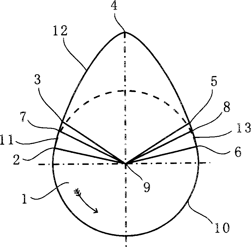
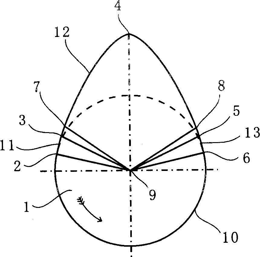
[0013] figure 1 It shows the schematic diagram of the intake and exhaust cam profiles on the camshaft of the existing internal combustion engine. This figure is extracted from the camshaft in the tenth "Gas Distribution Phase" of "Jiefang CA1091 Truck Atlas" published by Liaoning Science and Technology Publishing House Cam profile diagram. In the figure, 1 is the cam, point 9 is the center of the cam shaft, point 7 is the elimination of the valve clearance, point 8 is the beginning of the valve clearance, point 4 is the maximum lift of the valve, point 6-point 1 is the base circle of the cam 10, point 2- Point 3 is the valve opening buffer section 11, point 3-point 4-point 5 is the working section 12, and point 5-point 6 is the valve closing buffer section 13. The figure shows that the end point 3 of its valve opening buffer section 11 is located after the valve clearance point 7 is eliminated in the cold state, and the starting point 5 of its valve closing buffer section 13 ...
PUM
 Abstract
Description
Claims
Application Information
 - R&D
- Intellectual Property
- Life Sciences
- Materials
- Tech Scout
- Unparalleled Data Quality
- Higher Quality Content
- 60% Fewer Hallucinations
Browse by: Latest US Patents, China's latest patents, Technical Efficacy Thesaurus, Application Domain, Technology Topic, Popular Technical Reports.
© 2025 PatSnap. All rights reserved.Legal|Privacy policy|Modern Slavery Act Transparency Statement|Sitemap|About US| Contact US: help@patsnap.com


