Distance scale mounting mechanics for holographic aiming device and mounting method thereof

A distance scale and setting mechanism technology, which is applied in the field of weapon aiming equipment, can solve the problems of large volume and weight, poor stability, etc., and achieve the effect of fast distance scale and fast setting

Inactive Publication Date: 2006-11-15
无锡市星迪仪器有限公司
View PDF0 Cites 7 Cited by
  • Summary
  • Abstract
  • Description
  • Claims
  • Application Information

AI Technical Summary

Problems solved by technology

However, this purely mechanical mechanism has a large volume and weight, and its stability is not good.
Therefore, none of the existing holographic sights can solve this problem well

Method used


Image

  • Distance scale mounting mechanics for holographic aiming device and mounting method thereof
  • Distance scale mounting mechanics for holographic aiming device and mounting method thereof
  • Distance scale mounting mechanics for holographic aiming device and mounting method thereof

Examples


Embodiment Construction

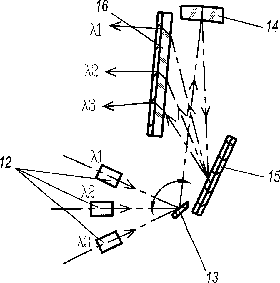
[0023] like Figure 3-8 As shown: the laser 12 of the holographic collimator is located at the focal point of an optical collimator 14, and after being refracted or reflected by the collimator 14, the laser beam emitted by the laser 12 becomes a parallel beam. The parallel laser beam shoots to the diffraction grating 15 at a certain angle, and the output is still a parallel light at a certain angle. The setting of the distance scale is actually to change the direction of the beam of light emitted from the hologram 16. The present invention provides two methods for changing the direction of the beam of light emitted from the hologram 16 when the positions of the hologram 16 and the diffraction grating 15 remain unchanged: (1) Two or more lasers with different wavelengths are used for illumination respectively, and the directions of the outgoing light beams of the diffraction grating 15 and the hologram 16 will change, and the purpose of labeling can be achieved by properly sele...


PUM


Abstract

The present invention relates to a holographic sighting device distance aiming ruble mounting mechanism and its mounting method. Said mounting mechanism includes the following several portions: two lasers, collimator, reflector and diffraction grating. Said invention also provides the connection mode of all the above-mentioned portions and the concrete action of every above-mentioned portion.

Description

technical field [0001] The invention relates to a sighting device for a weapon, in particular to a setting technology for a distance scale of a holographic sight. Background technique [0002] The principle of the existing holographic sight is as follows: figure 1 and figure 2 As shown, a high-quality laser diode 0 or 7 is used to emit a beam of laser light, which is collimated by the optical system 1 or 9 to become a parallel beam obliquely incident on a grating plane 3 or 10, and the first-order diffracted light emitted by the grating is still It is a parallel laser beam, and the laser beam is incident on the holographic surface 5 or 11 carrying the reticle pattern, and the human eye can see the reticle pattern through the -1 order diffracted beam emitted from the holographic surface. Here, the function of the grating is mainly to compensate the aiming error caused by the laser wavelength drift. Because as the temperature changes, the wavelength of the beam emitted by ...

Claims


Application Information

Patent Timeline
IPC IPC(8): G02B23/00
Inventor 安宝林李东跃张景鸫
Owner 无锡市星迪仪器有限公司
Why Eureka
Try Eureka