A laser marking method

A laser marking method and laser marking machine technology, which are applied in the field of laser marking, can solve problems such as burrs on trademarks, color difference, and crooked label stickers, and achieve the effect of improving installation stability and avoiding shaking of the marking head

Active Publication Date: 2021-01-26
杜拉维特(中国)洁具有限公司
View PDF6 Cites 0 Cited by
  • Summary
  • Abstract
  • Description
  • Claims
  • Application Information

AI Technical Summary

Problems solved by technology

[0004] The present invention intends to provide a laser marking method to solve the problems of crooked, missing, chromatic aberration and burrs on the trademark caused by the existing marking method

Method used


Image

  • A laser marking method
  • A laser marking method
  • A laser marking method

Examples


Embodiment 1

[0033] A laser marking method of the present invention comprises the following steps:

[0034] A. Install a positioning device with mounting holes 3 on the surface of the workpiece;

[0035] B. Spray the glaze from the mounting hole 3 of the positioning device in step A to the surface of the workpiece;

[0036] C. Install the laser marking machine on the mounting hole 3 of the positioning device, and start the laser marking machine for marking. In this embodiment, the laser marking machine adopts the BML-1x30-GC laser marking machine of Sernovi Company. When marking, the marking intensity of the laser marking machine is 300%, and the marking speed is 400 mm / s. The standard frequency is 100kHz.

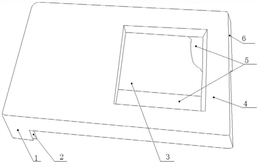
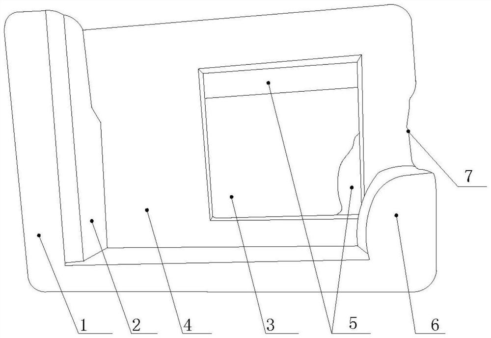
[0037] Such as figure 1 with figure 2 As shown, the positioning device described in step B includes a rectangular positioning body 4, a rectangular mounting hole 3 is provided on the positioning body 4, and an abutment plate 6 is integrally formed on the short side of the right si...

Embodiment 2

[0045] The difference between this embodiment and Embodiment 1 is that, as Figure 5 As shown, the interior of the gasket 9 in this embodiment is hollow to form a cavity 13, and a spring 11 is installed vertically in the cavity 13 to increase the elasticity of the gasket 9, and two suction holes 12 are provided at the bottom of the gasket 9 , The four outer walls of the gasket 9 are also provided with suction holes 12 , and each suction hole 12 on the gasket 9 communicates with the cavity 13 .

[0046] During specific use, put the end of the gasket 9 with the air suction hole 12 downward into the installation hole 3, and then manually press the gasket 9 vertically downward, so that the gasket 9 shrinks, and the spring 11 in the gasket 9 also Compressed, at this time the gas in the cavity 13 is squeezed out from the suction hole 12; the volume of the compressed gasket 9 becomes smaller, and the depth of the jack 10 on it also becomes smaller, which is convenient for inserting t...


PUM


Abstract

The invention relates to the technical field of ceramic processes, in particular to a laser marking method. The laser marking method comprises the following steps: A, mounting a positioning device with a mounting hole in the surface of a workpiece; B, spraying glaze to the surface of the workpiece from the mounting hole of the positioning device in step A; and C, mounting a laser marking machine on the mounting hole of the positioning device and starting the laser marking machine to mark. The problems that by an existing marking method, trademarks are skewed and lost, chromatic aberration exists, and the trademarks have deckle edges are solved.

Description

technical field [0001] The invention relates to the technical field of ceramic technology, in particular to a laser marking method. Background technique [0002] Toilets are the most common sanitary ceramics in people's lives. The production of toilets generally includes processes such as product design, slurry preparation, grouting, firing, and glazing. Existing toilets will be marked with trademarks on the surface after they are manufactured. [0003] The traditional marking method is to manually paste the trademark paper after glazing, and then enter the kiln and sinter together with the porcelain to form a permanent trademark pattern. This marking method has the following technical problems: 1. Using manual labeling will easily lead to trademark stickers. 2. Due to the printing quality of the label paper, it is easy to cause missing or color difference in the printed label; 3. The color of the label fired at high temperature will be too dark or too light, or there will b...

Claims


Application Information

Patent Timeline
Patent Type & Authority Patents(China)
IPC IPC(8): B23K26/362B23K26/70
CPCB23K26/362B23K26/361B23K26/702
Inventor 孔科斯琴
Owner 杜拉维特(中国)洁具有限公司
Why Eureka
Try Eureka