
Anti-rotation quick connector

一种连接器组件、快速的技术,应用在套筒/插座连接、联轴器、管接头等方向,能够解决螺纹尺寸昂贵、增加材料、增加加工时间等问题

Inactive Publication Date: 2006-11-22
TI GRP AUTOMOTIVE SYST LLC
View PDF4 Cites 12 Cited by
  • Summary
  • Abstract
  • Description
  • Claims
  • Application Information

AI Technical Summary

Problems solved by technology

Changing thread size per port is expensive because changing thread size makes machining different, increases material for larger thread sizes, increases machining time, and reduces batch size of brake tube nuts

Method used


Image

  • Anti-rotation quick connector
  • Anti-rotation quick connector
  • Anti-rotation quick connector

Examples


Embodiment Construction

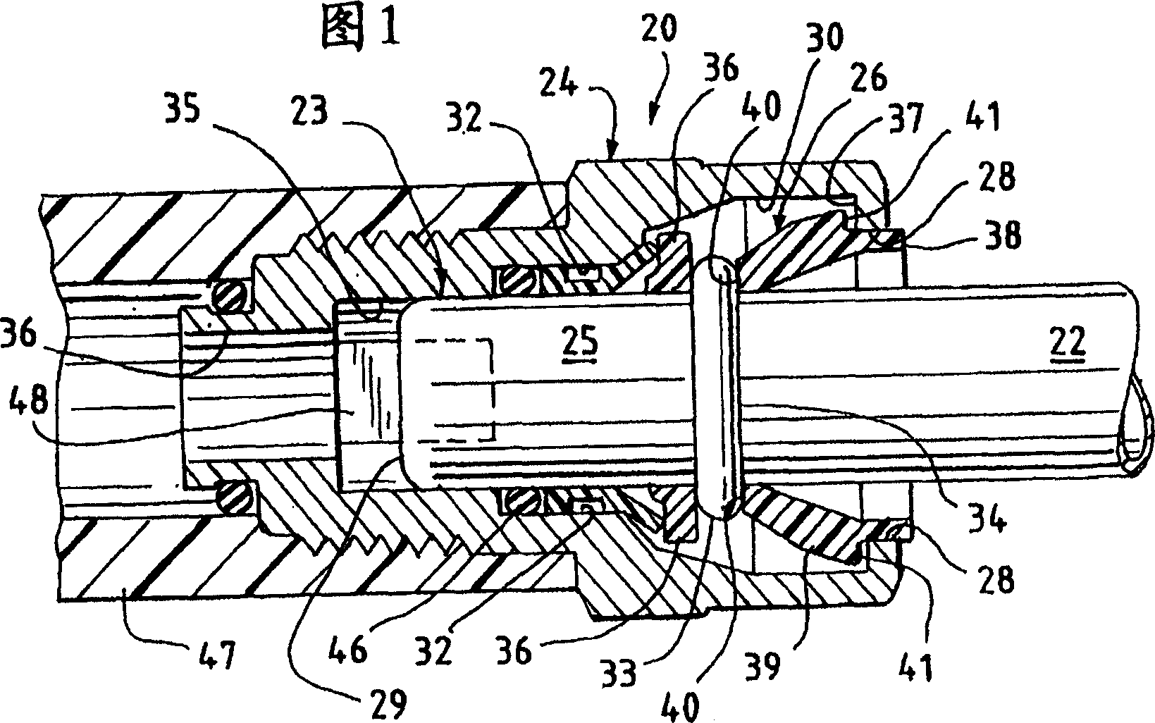
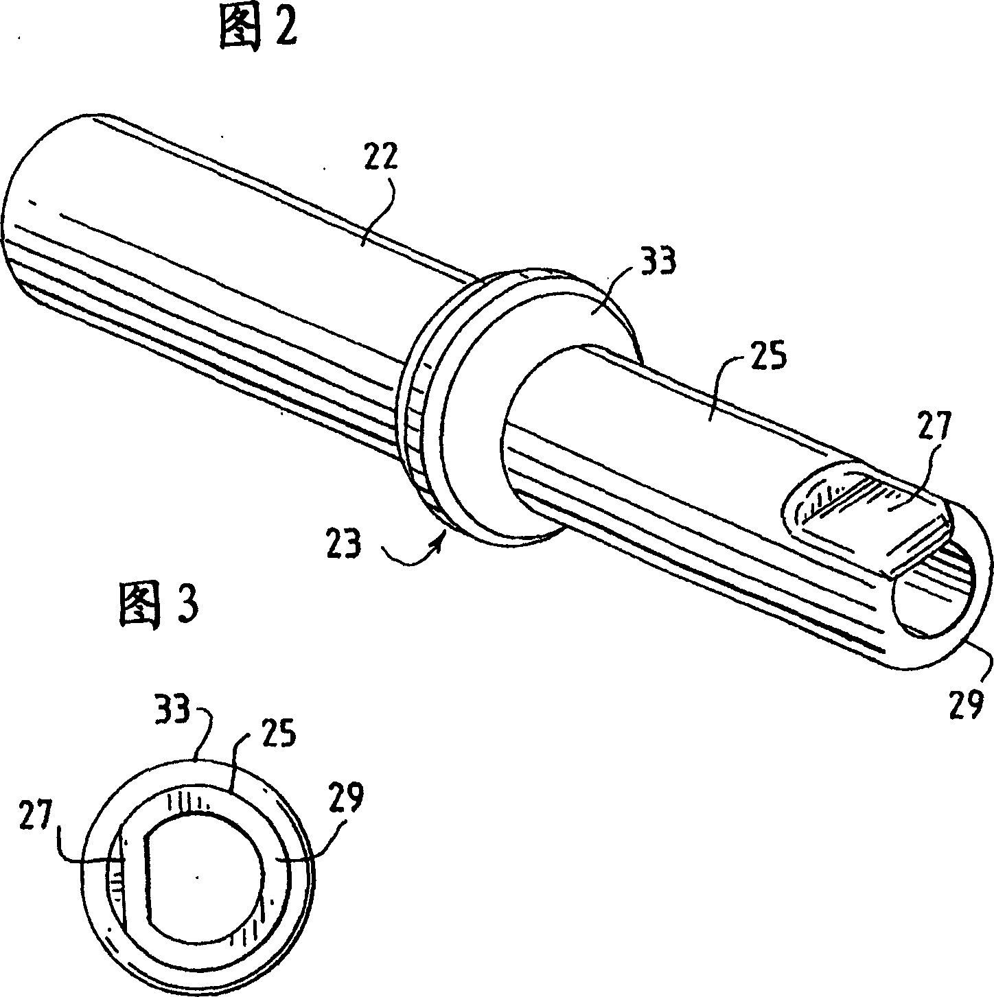
[0033] Figure 1 shows a cross-sectional view of a quick connector assembly, generally indicated at 20, embodying the teachings of the present invention. It includes a fluid fitting 22 and a body or housing 24 . A retainer 26 provides a releasable connection between the fluid system tubing 22 and the body 24 . The main body 24 is connected to a flexible hose 47 which connects the rest of the fluid system. This connector connection is generally similar to the quick connector disclosed in US Patent 5,161,832, which is hereby incorporated by reference.

[0034] The invention is suitable for various fast connector connection devices. Patents 5,257,833, 5,324,082, 5,395,140, ​​5,449,848, 5,628,531 and 6,086,118 are examples of quick connectors suitable for use with the present invention. It is envisioned that the present invention may also be used with various other known quick connector connection arrangements.

[0035] Tube 22 is a rigid metal tube. It comprises an end region...


PUM


Abstract

A quick connector coupling assembly comprising a body, a tube, and a retainer to secure the tube in the body. The body defines an internal cavity extending from an opening. The tube has an endform extending through the opening and into the internal cavity. The endform has a tip and an engagement surface. The engagement surface of the endform coacts with a locking surface associated with the body or the retainer to resist rotational movement of the tube relative to the body.

Description

technical field [0001] This application claims the benefit of US Provisional Application No. 60 / 657996, filed March 1, 2005. The present invention relates to a quick connector for releasably securing metal tubing in a fluid system. More particularly, it relates to quick connectors that prevent rotation of connected pipes. Background technique [0002] Quick connectors are used to assemble rigid fluid lines or fittings to mating components such as hoses, or fluid systems. Quick connector assemblies include some form of body or housing that defines an open receptacle having an inner cylindrical surface of varying diameter that cooperates with an inserted tubing. [0003] The aforementioned tube has a free end which mates with the connector body receptacle. A retainer releasably connects the other two components together. [0004] All quick connector ends allow the tube to rotate relative to the quick connector body. This relative rotational movement is undesirable in some...

Claims


Application Information

Patent Timeline
Patent Type & Authority Applications(China)
IPC IPC(8): F16L21/08F16L37/00
CPCF16L37/0987F16L37/144F16L2201/10F16L37/0885B65D51/24B65D85/00
Inventor 斯蒂芬·H·冈德森
Owner TI GRP AUTOMOTIVE SYST LLC
Learn More