Method for confirming stress intensity factor distribution on member crack tip

A technology of stress intensity factor and crack front, applied in complex mathematical operations, etc., can solve problems such as low accuracy, low calculation efficiency, and poor mathematical simulation effect

Inactive Publication Date: 2006-11-22
ZHEJIANG UNIV OF TECH
View PDF0 Cites 7 Cited by
  • Summary
  • Abstract
  • Description
  • Claims
  • Application Information

AI Technical Summary

Problems solved by technology

[0005] In order to overcome the disadvantages of low calculation efficiency, poor mathematical simulation effect and low precision of the existing method for determining the distribution of stress intensity factors at the crack front of structural parts, the present invention provides a unique method for determining the distribution of stress intensity factors at the front edge of structural parts method, with high precision and high efficiency to determine the distribution of the stress intensity factor of the curved three-dimensional crack front along the crack front; the actual execution efficiency of this method can be dozens of times or even hundreds of times higher than other existing methods

Method used


Image

  • Method for confirming stress intensity factor distribution on member crack tip
  • Method for confirming stress intensity factor distribution on member crack tip
  • Method for confirming stress intensity factor distribution on member crack tip

Examples


Embodiment 1

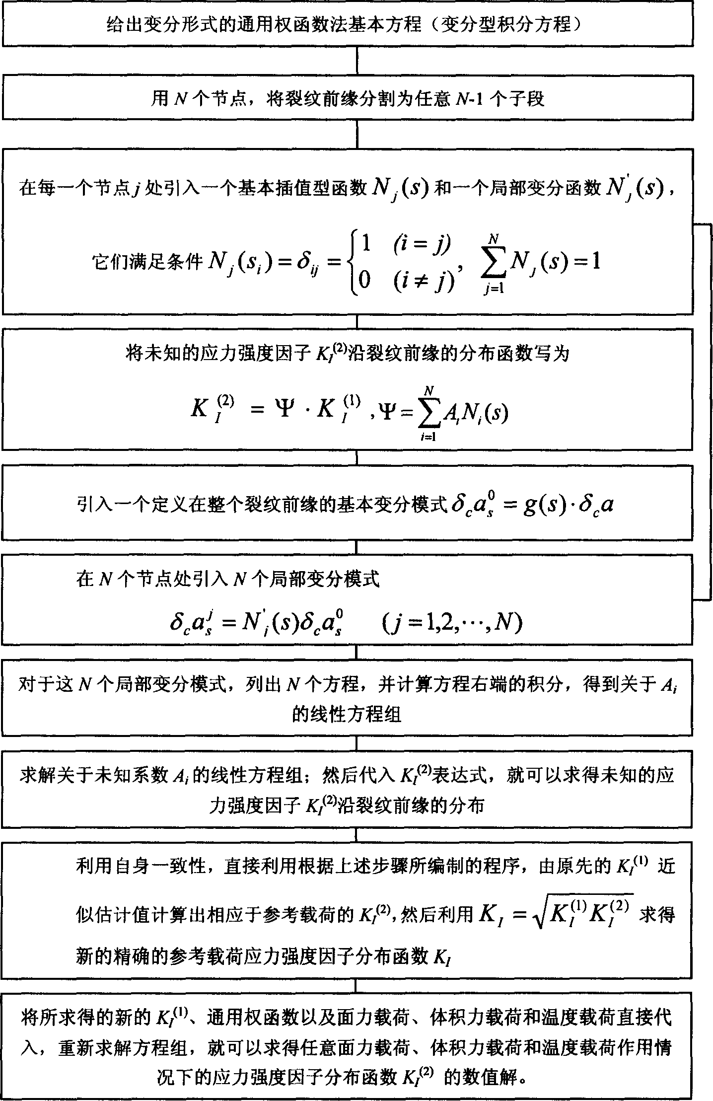
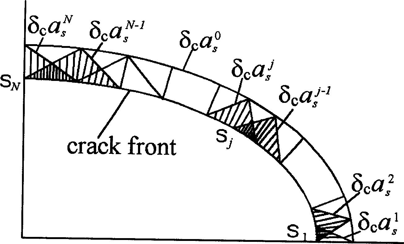
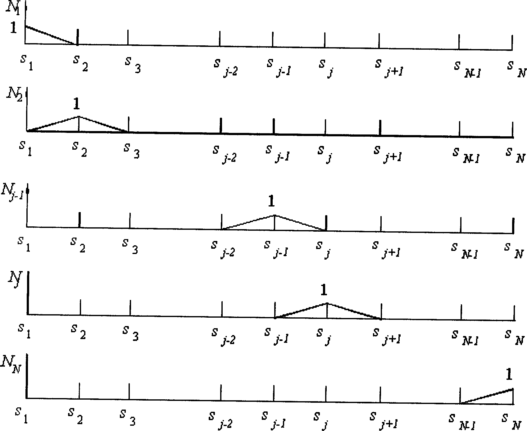
[0059] refer to figure 1 , figure 2 , image 3 , Figure 4 , Figure 5 , a method for determining the distribution of stress intensity factors at the crack front of structural parts, the method mainly includes the following steps (see attached figure 1 ):

[0060] (1) The basic equation of the general weight function method (variational integral equation) that gives the variational form of the problem to be solved, including thermal load, surface force load and body force load.

[0061] ∫ Γ 2 K I ( 1 ) K I ( 2 ) H δ c a ( s ) ds ...

Embodiment 2

[0089] refer to figure 1 , figure 2 , image 3 , Figure 4 , Figure 5 , Figure 6 , according to the method for determining the stress intensity factor distribution of the crack front of the structural member described in Example 1, the distribution of the stress intensity factor of the crack front of the semi-elliptical surface crack in the plate under thermal shock (thermal load) was determined. The figure below shows a semi-elliptical surface crack with a depth ratio of α / w=0.5 and a shape ratio of α / c=0.5, at Θ 0 = In the case of thermal shock at -300℃, the stress intensity factor distribution of the crack front changes with time. Among them, M is the dimensionless stress intensity factor, F o is the dimensionless time, φ is the position of the crack front (parameter angle), and Bi is the Biot number of the heat exchange condition at the time of impact. The distribution of the stress intensity factor along the crack front is determined for 60 time points in the fi...

Embodiment 3

[0092] refer to figure 1 , figure 2 , image 3 , Figure 4 , Figure 5 , Figure 7 , according to the method for determining the stress intensity factor distribution of the crack front of the structural member described in Example 1, the axial semi-elliptical surface crack in the circular tube acts simultaneously under the thermal shock (thermal load) and pressure shock (surface force load) (bearing The distribution of the stress intensity factor at the crack front under pressure-thermal shock) was determined. The figure below shows the axial semi-elliptical surface crack with a depth ratio of α / w=0.25 and a shape ratio of α / c=1 / 3, and the stress intensity factor distribution of the crack front changes with time under the pressure thermal shock of Rancho Seco process. Among them, K I is the stress intensity factor, t is the time, and φ is the position of the crack front (parameter angle). The stress intensity factor distribution of the crack front was determined for 8...


PUM


Abstract

The disclosed determining method for crack front stress intensity factor distribution of a structural member comprises: providing the thermal load, surface force load and body force load, as well as the general weight function base equation acted by any of three loads; dividing the front into N-1 subsegments by N nodes, and using a basic interpolation function N(s) and local variation function N'j(s) for every node j. This invention can determine the factor distribution for curve-type 3D crack with high precision and efficiency by finite modes and interpolation way.

Description

(1) Technical field [0001] The present invention relates to a method for determining the distribution of stress intensity factors at the crack front of structural parts in the field of structural safety analysis and evaluation and a computer calculation program design method, which are used to determine structural parts with high precision and high efficiency in the process of structural safety evaluation Distribution of the stress intensity factor (K) along the crack front in 3D crack front. (2) Background technology [0002] Generally, there are two methods to determine the stress intensity factor distribution of the crack front in structural parts by computer calculation. One is the direct method of elastic mechanics. It is necessary to perform elastic mechanical calculations on the body with cracks to determine the displacement field or stress field under the load; then according to the obtained displacement field or stress field, the Calculate and determine the K value...

Claims


Application Information

Patent Timeline
IPC IPC(8): G06F17/10
Inventor 卢炎麟
Owner ZHEJIANG UNIV OF TECH
Why Eureka
Try Eureka