
Radio frequency identification (RFID) system

一种视频、天线的技术,应用在无线电频率识别领域,能够解决降低RFID使用率等问题

Inactive Publication Date: 2006-11-22
CHUNG LAM ELECTRONICS
View PDF3 Cites 8 Cited by
  • Summary
  • Abstract
  • Description
  • Claims
  • Application Information

AI Technical Summary

Problems solved by technology

Users are forced to cooperate with many companies to build radio frequency identification (RFID) infrastructure equipment, and the inevitable difficulty of communication between companies reduces the utilization rate of RFID

Method used


Image

  • Radio frequency identification (RFID) system
  • Radio frequency identification (RFID) system
  • Radio frequency identification (RFID) system

Examples


Embodiment Construction

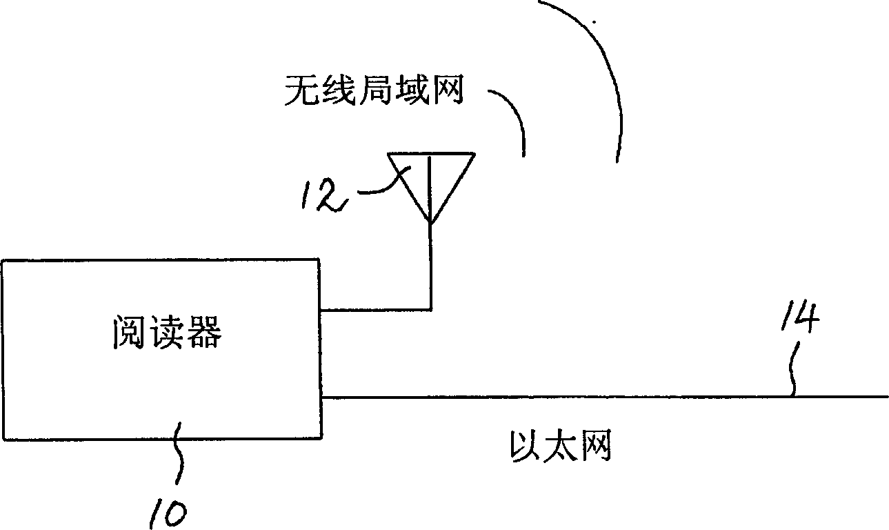
[0050] Such as figure 1 As shown, the redundant network multimedia RFID system of the present invention needs to use a wireless local area network (Wi-Fi) connection and an Ethernet connection at the same time to ensure the connectivity of the redundant network. In order to transmit radio frequency (RF) signals to the external environment, the RFID reader 10 in the system is connected to the wireless local area network through the antenna 12, and is also connected to other systems through the Ethernet cable 14, providing a redundant physical layer.

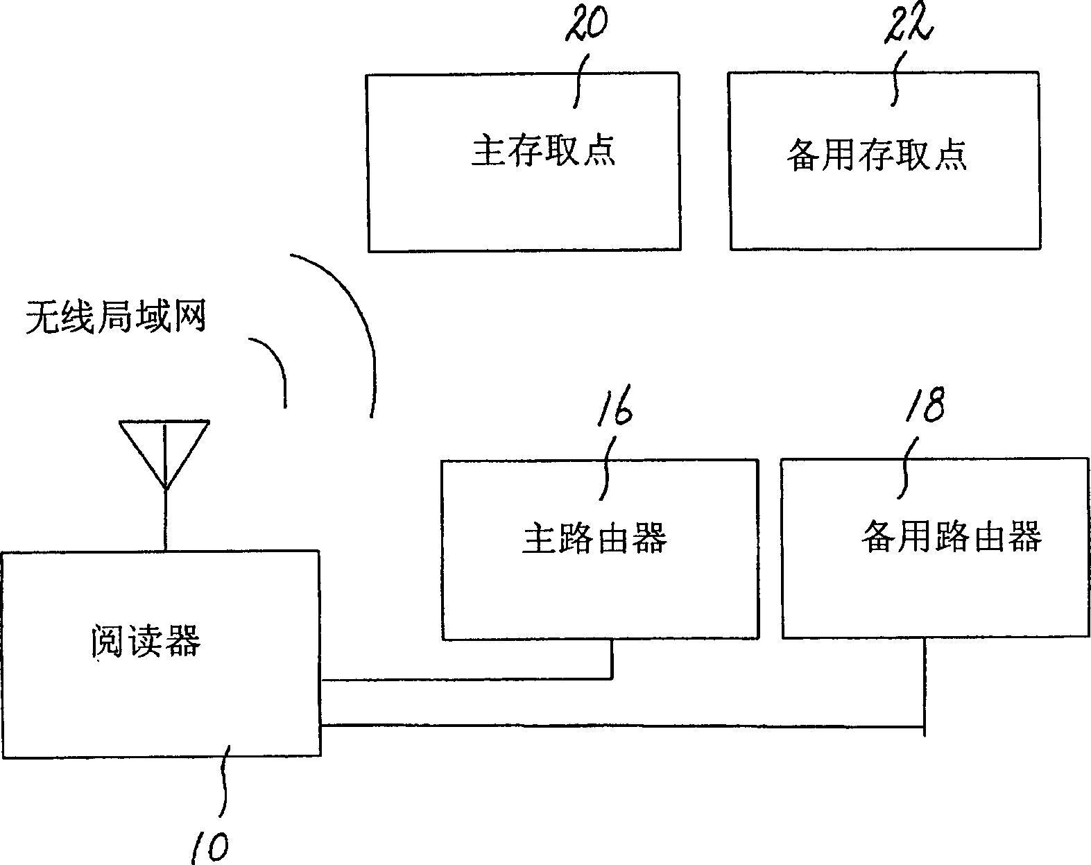
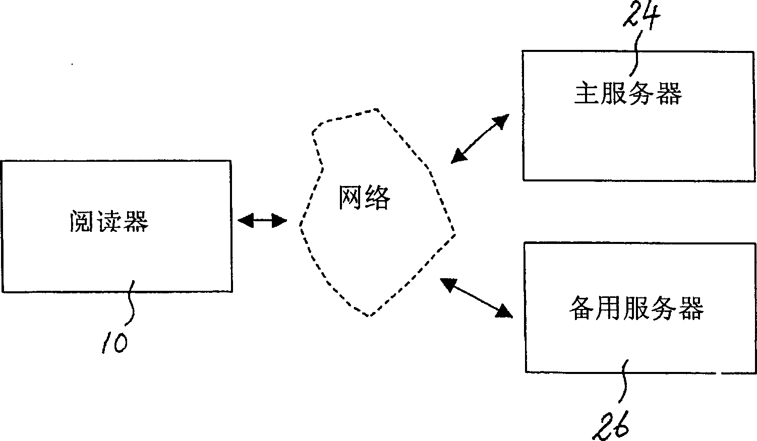
[0051] Such as figure 2 As shown, the system is set up to automatically find a primary router 16, a backup router 18, a primary access point (node) 20 and a backup access point (node) 22 for gateway redundancy. Such as image 3 As shown, the system is set up such that the RFID reader 10 automatically finds the main server 24 and the backup server 26 for backup redundancy. Even if neither server 24 nor 26 can be found, the syst...


PUM


Abstract

A group of technologies related to RFID reader and tag are described, including: redundant networked multimedia RFID reader, auto-ranging RFID reader, auto-planning RFID reader, smart active antenna RFID reader and novel RFID tags. These enabling technologies bring RFID reader operations into a new level of automation, capability and ease of implementation.

Description

technical field [0001] The present invention relates to radio frequency identification (RFID) technology, which is similar to bar code technology for unique identification of products, and specifically refers to the use of radio technology so as not to use optical line scanning bar code technology. Background technique [0002] RFID technology has now begun to be widely used around the world. Many US patents related to this technology include: US 4,075,632, US 4,739,328, US 5,030,807, US 5,777,561, US 5,828,693, US 5,850,181, US 5,912,632, US 5,995,019, US 6,154,136, US 6,288,629, US 6,449,7 [0003] However, there are many barriers to wider adoption of the technology. The difficulty of using radio frequency identification (RFID) technology in different environments and business activities is that it presents challenges to all system integrators. The reading operation of RFID requires comprehensive knowledge of the following disciplines, including RF circuits, antennas, ra...

Claims


Application Information

Patent Timeline
Patent Type & Authority Applications(China)
IPC IPC(8): G06K7/00
CPCG06K7/0008G06K19/0723H01Q1/2208H01Q9/16
Inventor 黎建宇王安勇尹德奇黄汉辉曾毅明马百叶高炳文张志超
Owner CHUNG LAM ELECTRONICS
Learn More