Optical finger print image forming device

An optical device, fingerprint image technology, applied in the field of fingerprint identification, can solve the problems of small thickness, unsatisfactory, etc.

Inactive Publication Date: 2006-11-22
萨热姆安全公司
View PDF1 Cites 5 Cited by
  • Summary
  • Abstract
  • Description
  • Claims
  • Application Information

AI Technical Summary

Problems solved by technology

[0014] Therefore, the imaging device described in WO 01/88835 is unsatisfactory in terms of obtaining a fingerprint image of g

Method used


Image

  • Optical finger print image forming device
  • Optical finger print image forming device
  • Optical finger print image forming device

Examples


Embodiment Construction

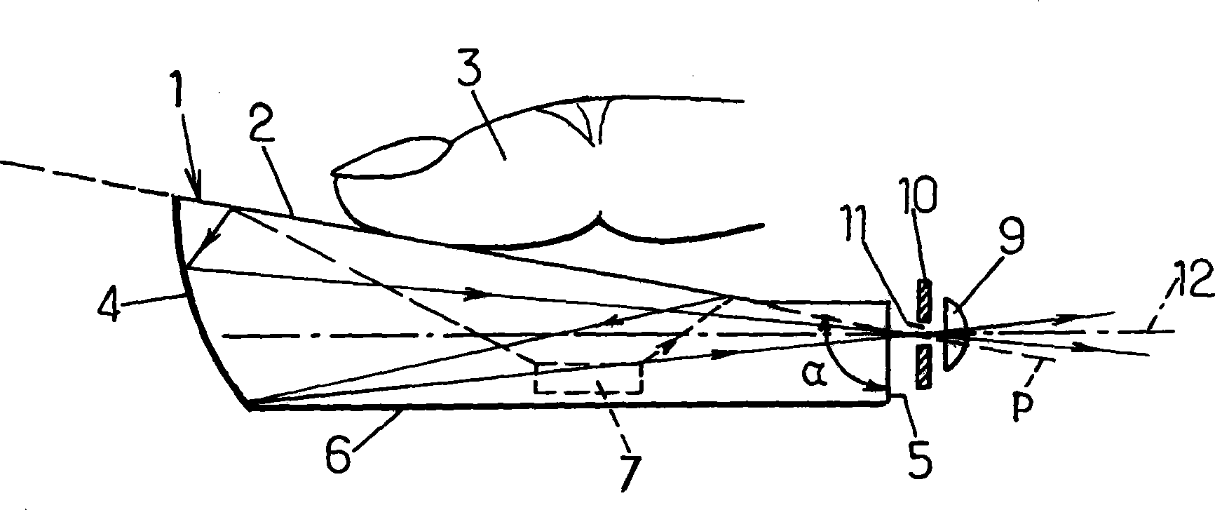
[0026] First, refer to figure 1 , the imaging device according to the present invention comprises an optical plate 1 comprising

[0027] - a first main face 2 constituting the face on which a finger 3 whose fingerprint image is to be obtained is applied,

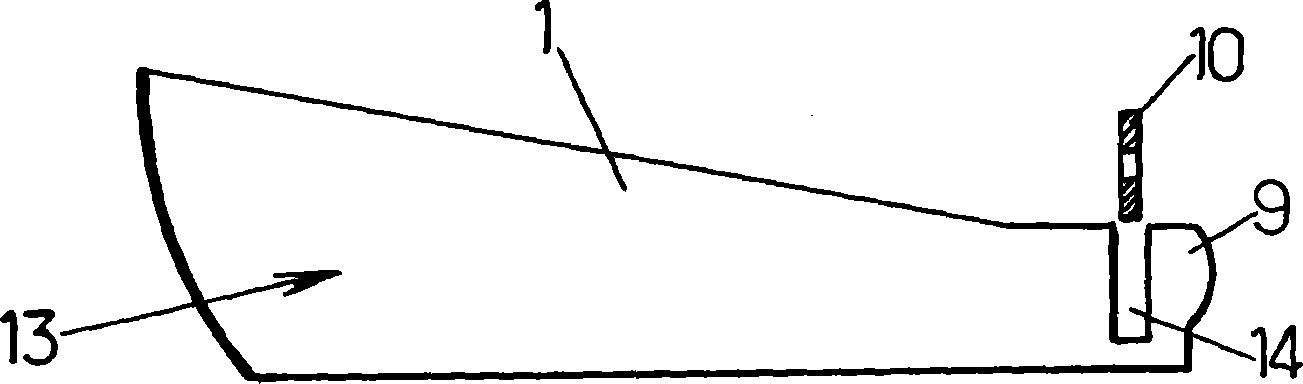
[0028] - a first side 4 shaped like a converging mirror, and

[0029] - a second side 5 , which is opposite the first side 4 and which forms the exit face of the optical plate 1 .

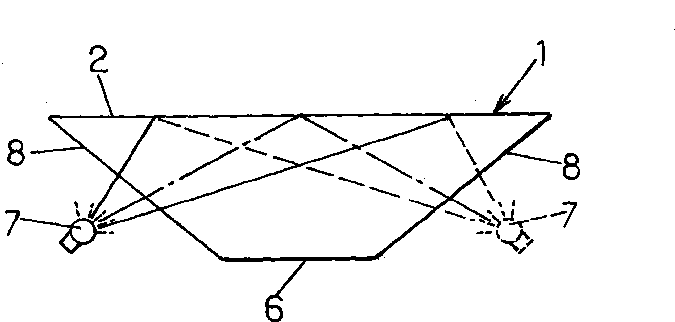
[0030] The optical plate 1 also has a second main surface 6 , which is opposite to the first main surface 2 and which can, for example, be substantially perpendicular to the exit surface 5 . Two other sides 8 (in figure 1 not visible) respectively extend between the two described first and second sides 4, 5, which will be referred to later.

[0031] The imaging device also includes at least one light source 7 for illuminating the first main surface 2 through the optical plate 1 . The light source can be placed under the optical plate 1, oppo...


PUM


Abstract

The invention relates to an optical device which is used to form a fingerprint image. The inventive device comprises an optical plate (1) having a first main face (2) on which a finger (3) is placed, a first side face (4) comprising a converging mirror, and a second side face (5) which is disposed opposite the first side face and which forms an output face, a focusing lens (9) being disposed opposite said output face (5). According to the invention, the first main face (2) forms an angle greater than 90 DEG with the output face (5), such that: the incidence of light rays on the first main face, inside the optical plate, is increased; the stray radiation at the output face is reduced,; and a thinner plate can be used.

Description

technical field [0001] This invention relates generally to the field of fingerprint identification and, more particularly, to improvements in optics for forming fingerprint images. Background technique [0002] It is here to be emphasized that the invention is only concerned with optical means capable of forming an image of a fingerprint, and that it does not concern the hardware downstream of said means for scanning / recording the obtained image, detecting the characteristic points of the fingerprint and Provide information about the person involved. [0003] Various embodiments of optical imaging devices for forming fingerprint images are known. [0004] In particular, International Publication WO 01 / 88835 discloses a fingerprint imaging device comprising: [0005] - an optical board having: [0006] a first main face constituting the face on which the finger whose fingerprint image is to be obtained is placed, [0007] a first side shaped like a converging mirror, and ...

Claims


Application Information

Patent Timeline
IPC IPC(8): G06K9/00
CPCG02B19/0023G02B19/0028G02B5/04G06V40/1324
Inventor 尚塔尔·科尔迪耶米格尔·布托内弗朗索瓦·里盖
Owner 萨热姆安全公司
Why Eureka
Try Eureka