Link station information transmission method based on multi-interface route equipment
A link state information and transmission method technology, which is applied in the field of link state information transmission based on multi-interface routing equipment, can solve problems such as network pressure on adjacent routers, achieve the effects of optimizing the flooding process, increasing the establishment speed, and avoiding occupation
- Summary
- Abstract
- Description
- Claims
- Application Information
AI Technical Summary
Problems solved by technology
Method used
Image
Examples
example 1
[0052] Example 1. The implementation process of forming the first adjacency relationship between routing device 1 and routing device 2.
[0053] In the process of forming the first adjacency relationship between routing device 1 and routing device 2, routing device 1 detects whether there is an established adjacency between it and routing device 2 after the first adjacency relationship being formed enters the 2WAY state Since the new adjacency is the first adjacency, routing device 1 determines that there is no established adjacency. In this way, routing device 1 sends a DD description packet carrying complete link state confirmation information to the routing equipment two.
[0054] After the first FULL adjacency relationship is formed between routing device 1 and routing device 2, the formation process of other new adjacency relationships is as described in Example 2 and Example 3 below.
[0055] For the convenience of description, the first adjacency that is being formed o...
example 2
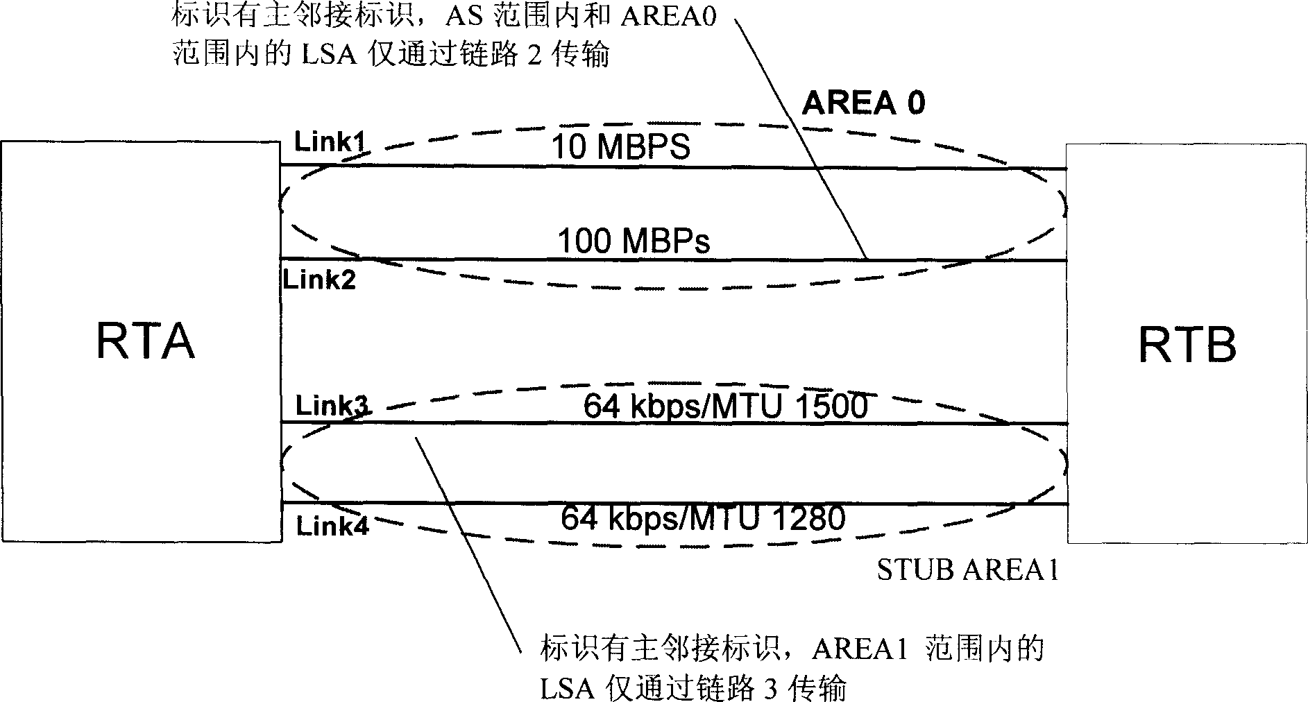
[0056] Example 2. When routing device 1 and routing device 2 have a FULL adjacency relationship of the same neighbor in the same area, the implementation process of forming a secondary adjacency relationship between routing device 1 and routing device 2 is as follows:
[0057] In the process of forming a secondary adjacency relationship between routing device 1 and routing device 2, after the secondary adjacency relationship enters the 2WAY state, routing device 1 detects whether there is a FULL adjacency of the same neighbor and the same area between it and routing device 2 relation. Since the adjacency being formed is a secondary adjacency, that is, there is a FULL adjacency between routing device 1 and routing device 2, routing device 1 determines that there is a FULL adjacency in the same area, and thus routing device 1 will carry the The DD description message of the link state confirmation information within the link range where the adjacency relationship is being formed...
example 3
[0058] Example 3. When routing device 1 and routing device 2 have FULL adjacencies in different areas of the same neighbor, the implementation process of forming a secondary adjacency relationship between routing device 1 and routing device 2 is as follows:
[0059] In the process of forming a secondary adjacency relationship between routing device 1 and routing device 2, after the secondary adjacency relationship enters the 2WAY state, routing device 1 detects whether there is a FULL adjacency in a different area of the same neighbor with routing device 2 . Since the adjacency that is being formed is a secondary adjacency, that is, there is a FULL adjacency between routing device 1 and routing device 2, routing device 1 determines that there is a FULL adjacency in a different area of the same neighbor. In this way, routing device 1 Send the DD description message carrying the link state confirmation information within the area where the secondary adjacency relationship is...
PUM
 Abstract
Description
Claims
Application Information
 - R&D
- Intellectual Property
- Life Sciences
- Materials
- Tech Scout
- Unparalleled Data Quality
- Higher Quality Content
- 60% Fewer Hallucinations
Browse by: Latest US Patents, China's latest patents, Technical Efficacy Thesaurus, Application Domain, Technology Topic, Popular Technical Reports.
© 2025 PatSnap. All rights reserved.Legal|Privacy policy|Modern Slavery Act Transparency Statement|Sitemap|About US| Contact US: help@patsnap.com

