Key switch device

A key switch and switch operation technology, applied in the field of connected key switch devices, can solve the problems of shaking and waste of the top of the key, and achieve the effects of preventing shaking in the left and right directions, increasing the plane area, and improving workability

Inactive Publication Date: 2006-12-06
MITSUMI ELECTRIC CO LTD
View PDF1 Cites 0 Cited by
  • Summary
  • Abstract
  • Description
  • Claims
  • Application Information

AI Technical Summary

Problems solved by technology

Therefore, it must be designed to ensure the key top interval of dimension D, so wasteful
[0006] Furthermore, there is a gap between the large connecting part 5 and the key top 2, and this gap produces a bad phenomenon that the key top shakes

Method used


Image

  • Key switch device
  • Key switch device
  • Key switch device

Examples


Embodiment

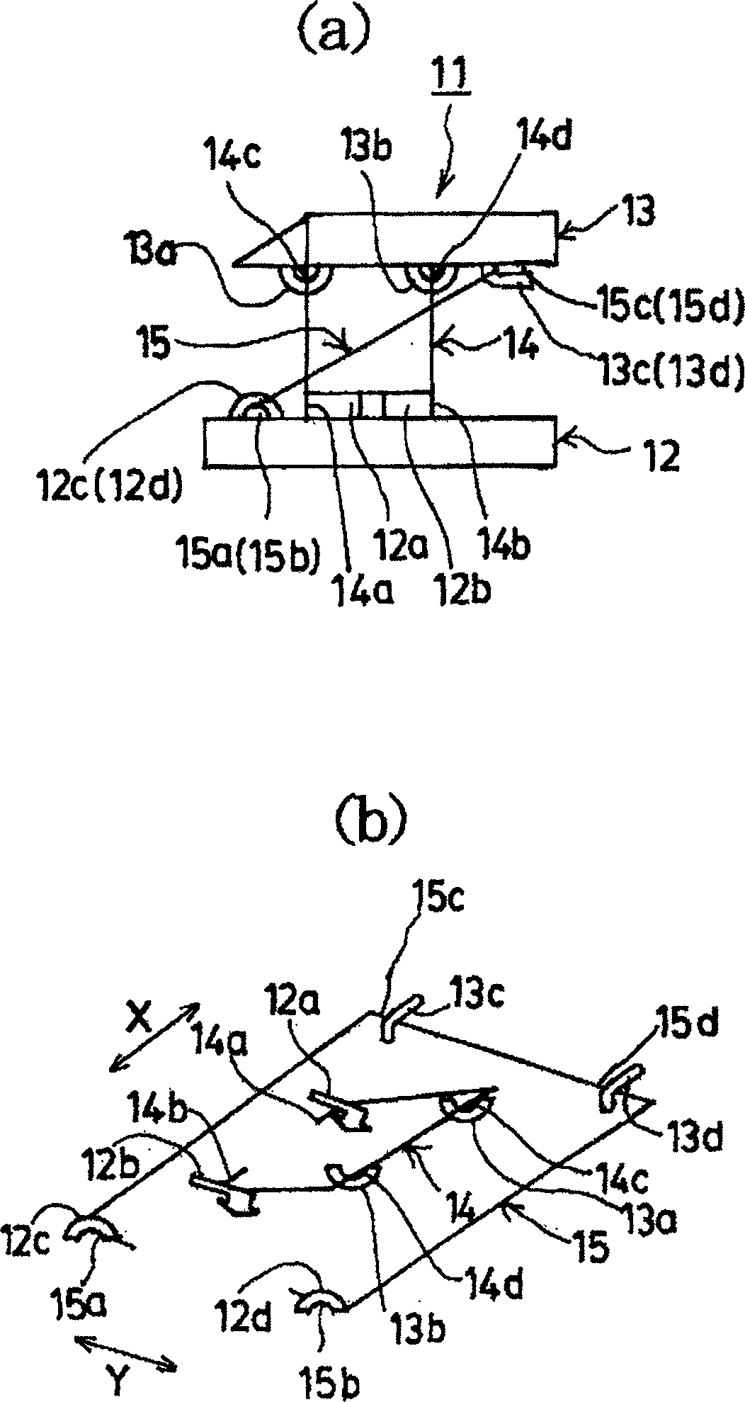
[0044] figure 1 (a) and (b) show one embodiment of the key switch device of the present invention. exist figure 1 In (a) and (b), 11 is a key switch device shown in a schematic diagram, and this key switch device 11 includes a substrate 12 and a key top 13 provided above the substrate 12 . A small connecting member 14 and a large connecting member 15 are mounted between the base plate 12 and the key top 13, and the small connecting member 14 and the large connecting member 15 are configured to rotate perpendicularly without contacting each other.

[0045] Moreover, sliding portions 14a and 14b are provided on both sides in the width direction X of the lower end portion of the small connecting member 14, and the sliding portions 14a and 14b are respectively slidably matched with the sliding guides 12a and 12b provided on the base plate 12. In addition, shaft support portions 14c and 14d are protrudingly provided on both sides in the width direction X of the upper end portion ...


PUM


Abstract

The invention relates to a key switch device which is characterized in that the key top part moves down smoothly without shaking when being pressed. The key switch device is also characterized in that when pressing the key switch (13), the upper and lower ends of the great connection component (15) of the key top part (13) can slide along the direction that parallels to the upper surface of base board (12), and the key top part (13) can move down directly; also, the left-right shake that the key top part (13) relatives to the great connection component (15) can be eliminated by pressing the right and left sides of the great connection component (15) set on the key top part (13).

Description

technical field [0001] The present invention relates to a key switch device, in particular to a connection type key switch device suitable for thin keyboards of notebook personal computers. Background technique [0002] Conventionally, for example, Patent Document 1 (Japanese Unexamined Patent Publication No. 2001-283675) and the like disclose a link type key switch. The key switch device disclosed in this Patent Document 1 generally has the structure shown in FIG. 6 . In the key switch device shown in FIG. 6, a rubber spring 3 is installed between a base plate 1 and a key top 2, and the key top 2 is formed so as to be able to move freely. Furthermore, between the base plate 1 and the key top 2, there are provided a small connecting member 4 and a large connecting member 5 which are not in contact with each other, and which are perpendicular to each other and rotate. The small connection part 4 is formed of synthetic resin, and the large connection part 5 is formed by bend...

Claims


Application Information

Patent Timeline
Patent Type & Authority Applications(China)
IPC IPC(8): H01H13/14
CPCH01H13/7065H01H3/122
Inventor 佐藤富雄
Owner MITSUMI ELECTRIC CO LTD
Why Eureka
Try Eureka