

Flow channel for a heat exchanger and heat exchanger with the same
A technology of heat exchanger and flow channel, applied in the field of heat exchanger
- Summary
- Abstract
- Description
- Claims
- Application Information
AI Technical Summary
Problems solved by technology
Method used
Image

Examples
Embodiment Construction
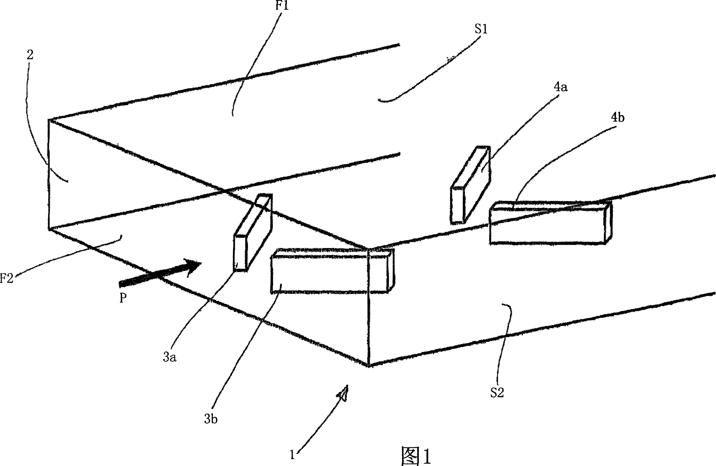
[0030] Figure 1 shows a simplified diagram of a flow channel 1, which is a rectangular tube with a rectangular inlet cross-section 2, two flat sides F1, F2 opposite each other and two narrow sides S1, S2. Flow channel 1 is passed through by a medium such as exhaust gas in the direction indicated by arrow P. Vortex generators 3 a , 3 b , 4 a , 4 b arranged in a V-shaped direction are arranged on the lower flat side F2 , which increase the turbulence of the fluid by generating vortices and at the same time prevent the formation of carbon deposits in the exhaust gas flow. This figure corresponds to the prior art described at the beginning of this description. According to the prior art, the vortex generators 3 a , 3 b and 4 a , 4 b arranged in pairs in each case in a V-shape and widening in the direction of flow in the shape of a diffuser are also referred to as finlets.
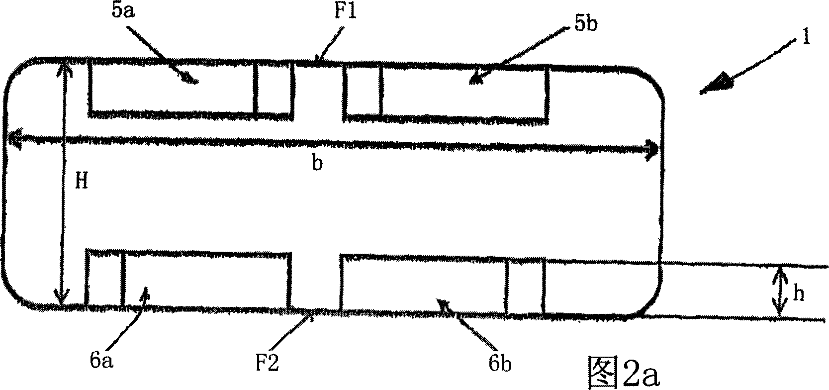
[0031] FIG. 2a shows a cross-section through a flow channel 1 formed by flat tubes, where pairs of small f...
PUM
 Abstract
Description
Claims
Application Information