Underwater gliding detector

A detector and shell technology, applied in the field of underwater gliding detectors, can solve the problems of limiting the distance and depth of the detector's ocean navigation, and achieve the effects of low cost, reduced power consumption, and compact size

Inactive Publication Date: 2006-12-13
ZHEJIANG UNIV
View PDF0 Cites 42 Cited by
  • Summary
  • Abstract
  • Description
  • Claims
  • Application Information

AI Technical Summary

Problems solved by technology

Frequent charging procedures greatly limit the distance and depth of the probe in the ocean

Method used


Image

  • Underwater gliding detector
  • Underwater gliding detector
  • Underwater gliding detector

Examples


Embodiment Construction

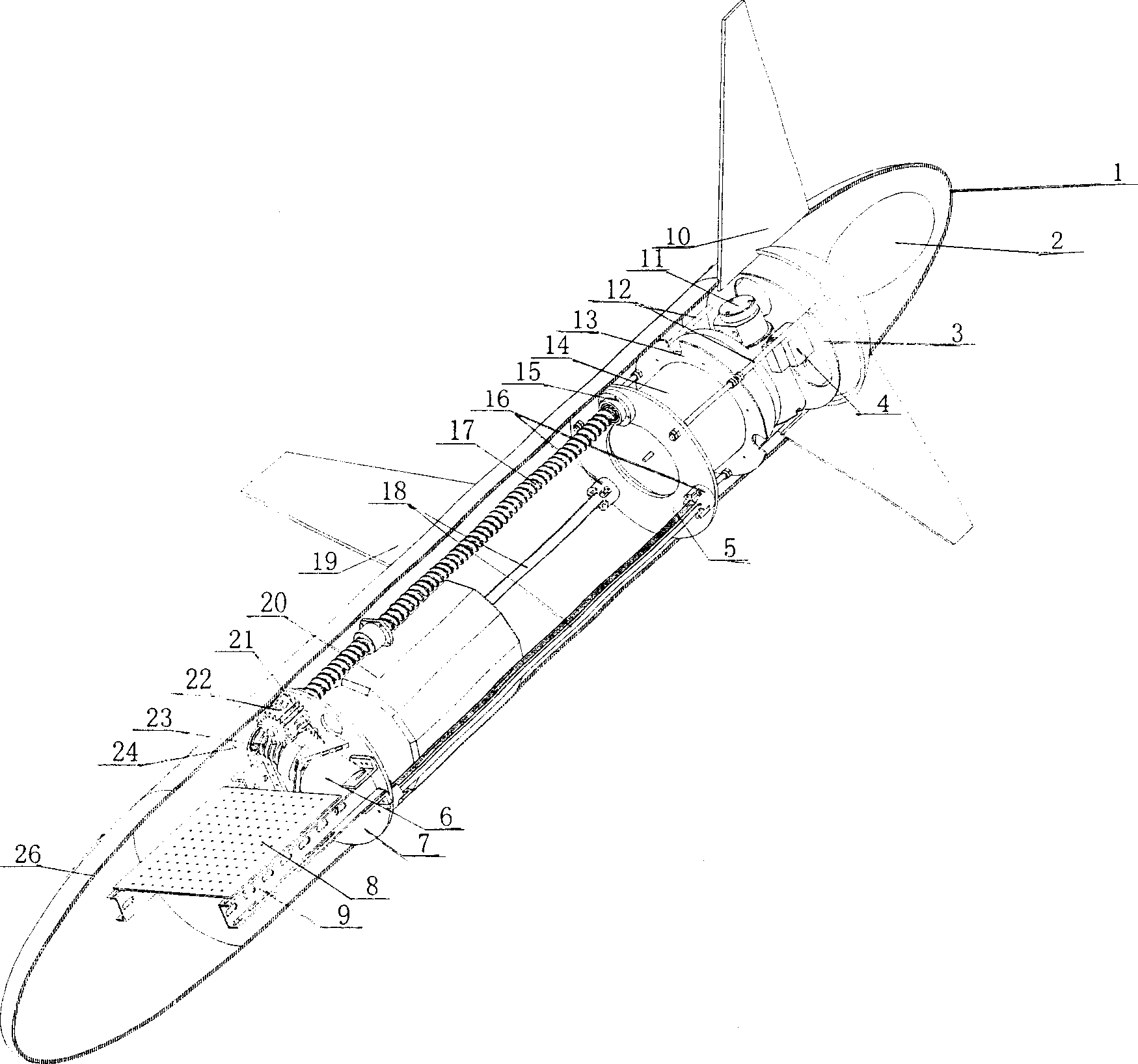
[0012] refer to figure 1 , the underwater gliding detector includes a gliding shell and a variable buoyancy system, an attitude adjustment system and a communication and navigation system installed in the gliding shell:

[0013] Gliding shell: a gliding shell composed of a protective shell 1, a horizontal wing 19 and an empennage 10, and a pressure-bearing shell 26 is arranged in the protective shell 1;

[0014] In order to reduce the motion resistance of the underwater gliding probe in seawater, the front and rear ends of the protective shell are elliptical, which satisfies the equation:

[0015] ( x 30 ) 2 + ( y 10 ) 2 = 1

[0016] Where: x, y are the horizontal and vertical coordinates of the longitudinal sec...


PUM


Abstract

The invention relates to an underwater glide detector, which comprises a glide frame, a variable buoyancy system, an attitude adjusting system and a communication navigation system, wherein when working, the driving device of attitude adjusting system can make the internal battery move along the axis of glide frame, to change the position of gravity center; the micro electromagnetic valve and micro pump of variable buoyancy system will cooperate to change the discharge volume of external oil vesicle, to change the buoyancy; therefore, the invention can realize saw-shaped motion in sea. Compared with present underwater robot, the invention has small volume, low cost and low energy consumption. And it can avoid screw and propeller, that powered by battery to operate in months.

Description

technical field [0001] The invention relates to an underwater gliding detector that can be widely used in water body water quality monitoring, underwater resource surveying and environmental monitoring. Background technique [0002] So far, most of the automatic detectors used for marine water quality monitoring, underwater resource surveying, and environmental monitoring research use propellers and other propulsion methods, so after working for a short time, they need to supplement power energy. Frequent charging procedures greatly limit the distance and depth of the probe in the ocean. Contents of the invention [0003] The purpose of the present invention is to propose a small and exquisite underwater gliding detector that can operate continuously for several months within a depth range of several kilometers according to a preset route. [0004] The underwater gliding detector of the present invention includes a gliding casing and a variable buoyancy system, an attitud...

Claims


Application Information

Patent Timeline
Patent Type & Authority Applications(China)
IPC IPC(8): B63C11/48
Inventor 杨灿军杜加友赵伟季龙陈鹰诸敏李江波陈正
Owner ZHEJIANG UNIV
Why Eureka
Try Eureka