Optical communication system

A technology of optical communication system and optical signal, applied in the field of optical communication system

Inactive Publication Date: 2006-12-13
NIPPON TELEGRAPH & TELEPHONE CORP
View PDF2 Cites 1 Cited by
  • Summary
  • Abstract
  • Description
  • Claims
  • Application Information

AI Technical Summary

Problems solved by technology

[0014] In addition, when a communication failure occurs in two or more communication terminals, a ring logical topology cannot be formed even if the above-

Method used


Image

  • Optical communication system
  • Optical communication system
  • Optical communication system

Examples


Embodiment Construction

[0097] Hereinafter, various embodiments of the present invention will be described with reference to the drawings.

[0098] (Embodiment 1)

[0099] In the following Embodiments 1 to 4, it is assumed that the input ports and The number N of output ports and the number n of communication terminals are described as "8" as an example, but not limited thereto, as long as N is an integer of 2 or more, and n is an integer of 2 or more and N or less.

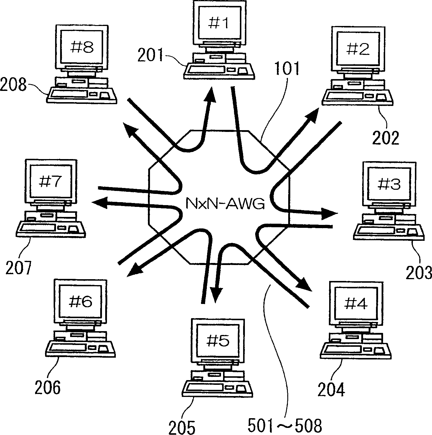
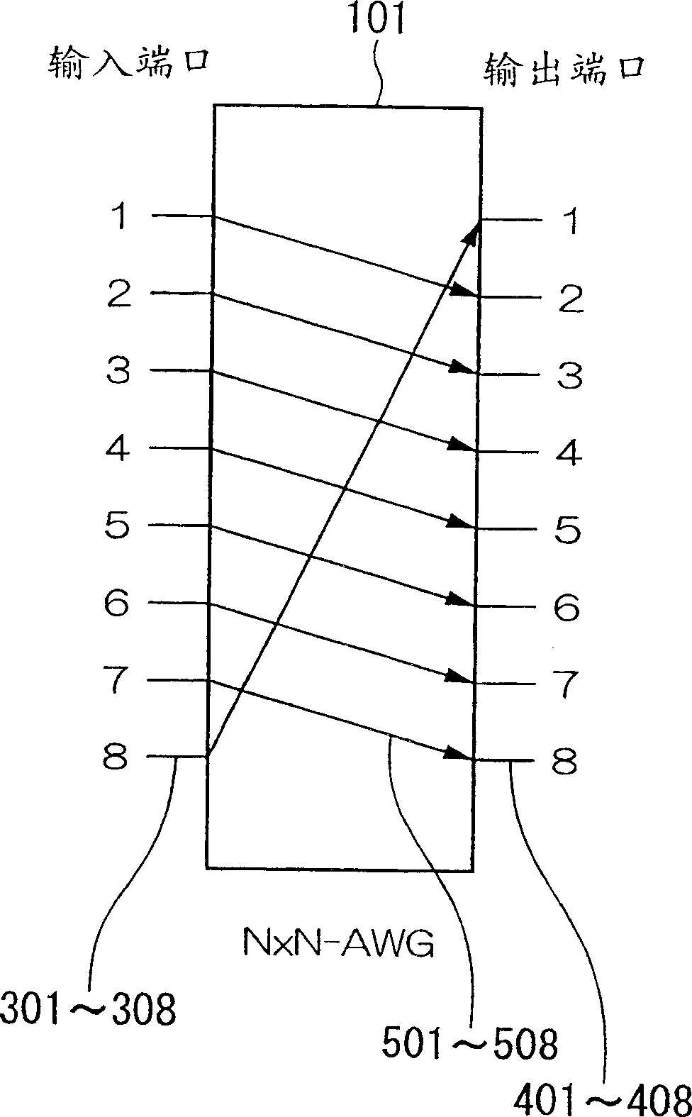
[0100] Figure 1A with Figure 1B Showing Embodiment 1 of the optical communication system of the present invention, Figure 1A represents the overall structure, Figure 1B An example of a transmission path between an input port and an output port in an N×N-AWG is shown.

[0101] Such as Figure 1A As shown, 101 is N×N (8×8 here)-AWG, which has 8 input ports 301-308 and 8 output ports 401-408, and the light input at one input port is output from different channels according to its wavelength. The ports are output, and the wavelen...


PUM


Abstract

An optical communication system is constructed which enables highly and flexible connection to communication nodes connected to a path establishment circuit, by utilizing wavelength-routing characteristics of a path establishment circuit such as an arrayed waveguide grating. The optical communication system has communication nodes having a signal output port and signal input port pair, and establishment circuit having multiple optical input ports and multiple optical out which are set so that optical signals input from the respective optical input ports are output to predetermined optical output ports corresponding to the wavelengths of the optical signals.

Description

[0001] This application is a divisional application of: [0002] Invention Name: Optical Communication System [0003] Application number: 200310116327.7 [0004] Application date: November 19, 2003 technical field [0005] The present invention relates to an optical communication system for connecting communication terminals. In particular, the present invention relates to utilizing the wavelength routing characteristic of an arrayed waveguide grating to connect a plurality of communication terminals in a highly reliable and flexible manner at low cost while sharing the light of a memory installed in each communication terminal at a low cost. Communication system (optical network system). In particular, the present invention relates to an optical communication system using an arrayed waveguide grating or the like, which can connect communication terminals in a highly reliable and flexible manner by utilizing wavelength routing characteristics. [0006] This specification ...

Claims


Application Information

Patent Timeline
IPC IPC(8): H04J14/02H04B10/12H04B10/20H04Q11/00
Inventor 田野边博正冈田显松冈茂登野口一人坂本尊森胁摂
Owner NIPPON TELEGRAPH & TELEPHONE CORP
Why Eureka
Try Eureka