Ceramic-overmoulding method and composite element obtained by this method

a technology of ceramic overmoulding and composite elements, which is applied in the direction of application, coating, rigid pipes, etc., can solve the problems of difficult to obtain intimate contact between the two associated materials, brittle material, and difficult machine, etc., to achieve reliable, flexible, easy to maintain in suit and hygienic

Inactive Publication Date: 2011-01-20
N C A TECH
View PDF1 Cites 1 Cited by
  • Summary
  • Abstract
  • Description
  • Claims
  • Application Information

AI Technical Summary

Benefits of technology

[0013]There is therefore still a need for composite ceramic elements specially adapted to the handling and packaging of fluids that are resistant to the thermal and mechanical stresses imposed, reliable, flexible, easy to maintain in suit and hygienic.

Problems solved by technology

On the other hand, ceramic is a brittle material and therefore very difficult to machine.
This association, despite its technical and technological benefits, is not without limitations.
Despite the possibility of working with ever-smaller tolerances (of the order of a micrometre), below a certain scale it in fact becomes difficult to obtain an intimate contact between the two associated materials.
The requirements of hygiene and purity have a direct impact on the production installations, which are also subject to restrictive and constantly changing legal regulations.
Furthermore, the mechanical performance characteristics of polymer materials, in particular thermoplastics, are strongly degraded at high temperature.
However, none of the articles described is intended to be subject to extreme temperature variations and therefore to excessive shear at the interface between the ceramic or metal part and the polymeric part due to high thermal expansion differences.
Consequently, none of the articles described in the prior art is able to withstand extreme thermal gradients and / or mechanical stresses.

Method used


Image

  • Ceramic-overmoulding method and composite element obtained by this method
  • Ceramic-overmoulding method and composite element obtained by this method
  • Ceramic-overmoulding method and composite element obtained by this method

Examples


Embodiment Construction

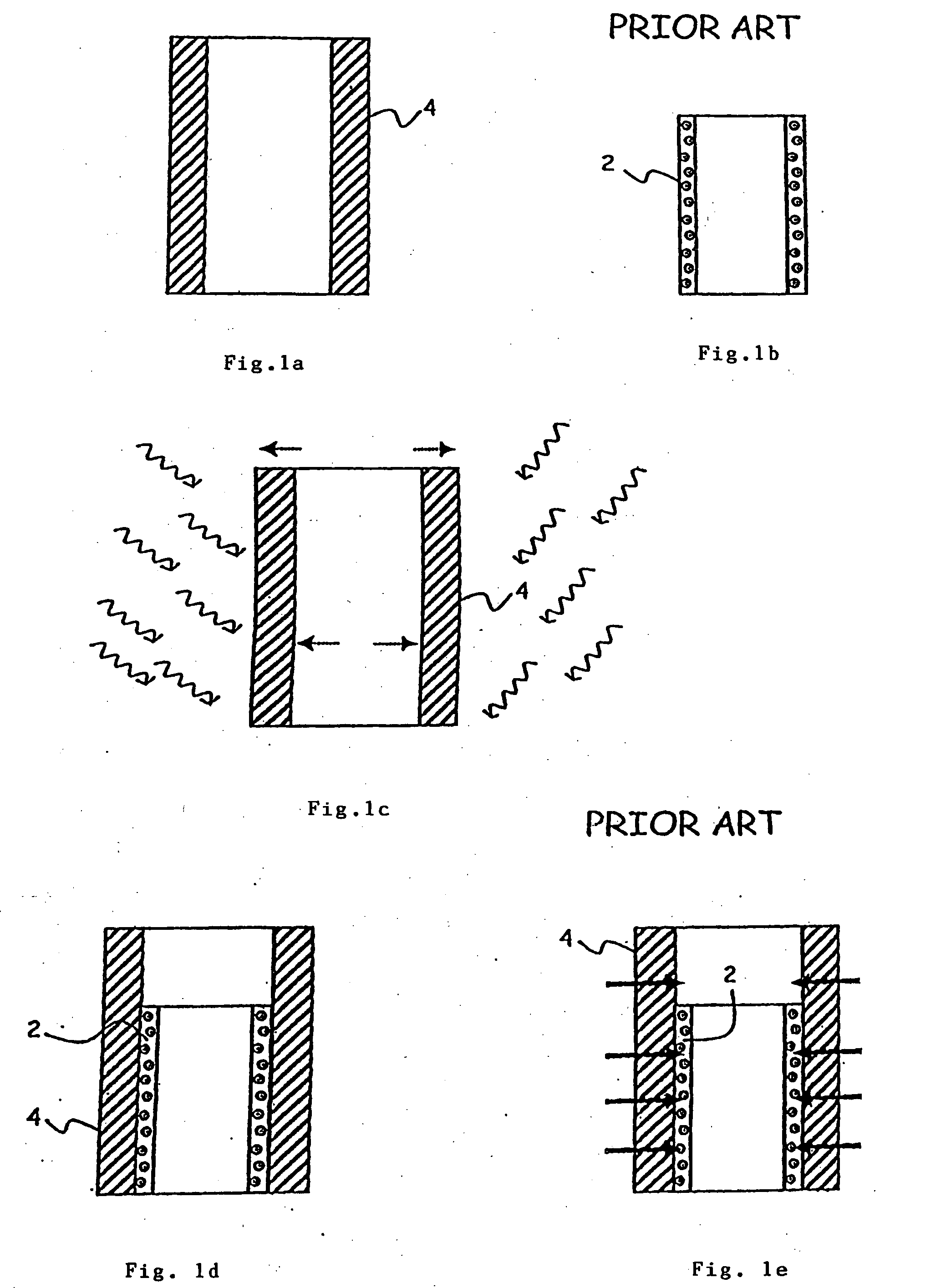
[0055]FIGS. 1a to 1e give the various steps of the hooping method developed previously (prior art) for assembling ceramic and metallic elements to produce composite pieces that can satisfy the constraints imposed by the packaging industries.

[0056]FIG. 1b shows an element in sleeve form made of ceramic 2, defined as a “female” element. The qualities of the ceramic makes such an element ideal for forming the internal sleeve of a pump chamber for the packaging of fluids, pasty or powdery products. However, as such, this sleeve is virtually unusable, since it is excessively difficult to join it to other pieces of a circuit without risk of damaging it. One solution is to set it in a cylinder make of stainless steel 4, as represented in FIG. 1d. This cylinder 4 can be provided, by different known methods (welding, brazing, moulding), with various added accessories (not shown, in the interests of clarity). This cylinder 4 is machined internally so that its internal diameter roughly corresp...


PUM

PropertyMeasurementUnit
depthaaaaaaaaaa
depthaaaaaaaaaa
temperatureaaaaaaaaaa

Abstract

A member of an element for feeding fluid and pasty products in cylinder or sleeve form, able to withstand high thermal transitions, comprises, arranged concentrically relative to each other, a part made of ceramic material (6, 16) intended to come into contact with the fluid and a support made of polymer material (14, 22) overmoulded on the part made of ceramic material (6, 16). The part made of ceramic material (6, 16) has, on its external lateral face, at least one relief (24) comprising at least one dextrogyral helical groove and at least one levogyral helical groove that extend over the surface of the ceramic part in contact with the support made of polymer material which both prevent any relative movement of this part (6, 16) and of the support (14, 22), and distribute the tensions that can be produced by high temperature differentials.

Description

FIELD OF THE INVENTION[0001]The invention relates to a method making it possible to manufacture composite ceramic elements especially suited to the handling and packaging of fluids or pasty or powdery products, in particular for the food, pharmaceutical and chemical industries.[0002]The invention also relates to elements produced by such a method.STATE OF THE ART[0003]The benefits of ceramic materials, of high technicality, are known: good hardness, mechanical strength, high resistance to wear and corrosion, low friction coefficient, low rate of salting-out of particles, low thermal expansion. Huge progress has also been made in the quality of the moulding, which makes it possible to produce pieces of unrivalled precision and surface state. On the other hand, ceramic is a brittle material and therefore very difficult to machine. Consequently, ceramic is frequently associated with a support material.[0004]The applicant has thus specialized in the manufacture of feed elements, such as...

Claims


Application Information

Patent Timeline
Patent Type & Authority Applications(United States)
IPC IPC(8): F16L9/14B29C69/00
CPCB29C45/14311B32B2307/746B29C45/14598B29C45/14778B29C2045/14877B29K2709/02B32B9/005B32B9/045B32B27/281B32B27/285B32B27/286B32B27/288B32B27/308B32B1/08B32B2307/306B32B2307/542B32B2307/558B32B2307/714B29C45/14549
Inventor GUILLOTIN, FRANCOISRUFFALDI, ALDO
Owner N C A TECH
Why Eureka
Try Eureka