A roll as well as a ring for such a roll

A roll and roll ring technology, applied in the field of rolls and rings used for such rolls, can solve the problems of failure, fatigue, loss, etc.

Active Publication Date: 2006-12-20
HYPERION MATERIALS & TECH SWEDEN AB
View PDF1 Cites 3 Cited by
  • Summary
  • Abstract
  • Description
  • Claims
  • Application Information

AI Technical Summary

Problems solved by technology

However, this solution was not successful due to the positioning of the springs in the roller ring and spacer ring set etc. and due to fatigue problems
In fact, the tension or spring force of the Belleville spring in question should be possible to readjust, i.e. by means of a set of screws, but due to its positioning inside the set of removable rings, the spring is continuously subjected to a force which makes The spring deforms or rather flattens, wh...

Method used


Image

  • A roll as well as a ring for such a roll
  • A roll as well as a ring for such a roll

Examples


Embodiment Construction

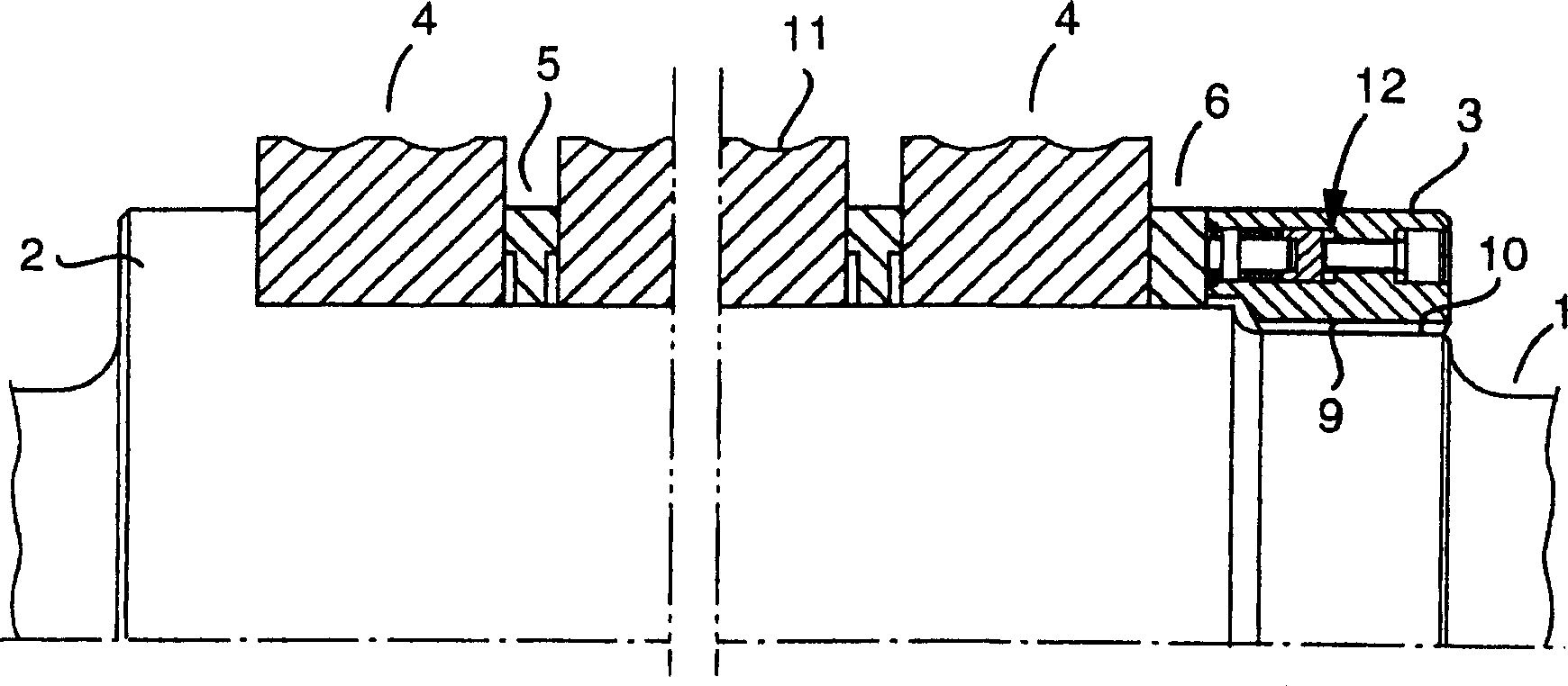
[0015] figure 1 shows a composite roll comprising, in the conventional manner, a drivable shaft or roll shaft 1 with two axially spaced apart stop rings 2, 3, one of which, stop ring 2, is fixed, And the other is detachable from the lock nut 3 on the shaft. In this example, the fixed stop ring 2 is in the form of an annular shoulder integrally formed with the remainder of the shaft. However, it is also feasible to manufacture the fixed stop ring 2 in the form of a separate detachable ring, which is axially locked relative to the shaft in a suitable manner.

[0016] A plurality of detachable rings, some of which are roller rings 4 and others of which are spacer rings 5 ​​, are arranged between the fixed stop ring 2 and the separable jam nut 3 . Between the lock nut 3 and the roller ring 4 located closest to it there is an additional ring 6 , the design of which may differ from that of the spacer ring 5 and which is hereinafter referred to as the fastening ring. In general, t...


PUM


Abstract

In a first aspect, the invention relates to a ring, preferably in the form of a lock nut, made for combi rolls, which ring includes at least one spring device (12) in which a mechanical compression spring (18) is included that acts between, on one hand, a front press body (19) that is movable to and fro in order to constantly forward a spring force generated by the compression spring and, on the other hand, a support body (20), which may assume a fixed position, but which is adjustably movable by way of a screw (26) in order to alter the tension in the compression spring. In another aspect, the invention relates to a combi roll in which the ring according to the invention is included.

Description

technical field [0001] In a first aspect, the invention relates to a roll comprising a drivable roll shaft and two axially spaced apart stop rings, one of which is fixed and the other is a lock nut, a plurality of other rings being mounted Between the snap rings, one or more of these other rings are roller rings. [0002] Rolls of this type substantially as described above are referred to as composite rolls by those skilled in the art. In practice, such rolls are used for hot or cold rolling of long and narrow metal products, such as metal wire, rod, pipe, etc. For this purpose, these roll collars or rings, ie rings for performing metal forming, unlike spacer rings or the like, are formed with a plurality of circumferential grooves generally having a semicircular cross-sectional shape. Background technique [0003] An important factor for the long-term proper functioning of such rolls is that the different rolls and spacer rings are fixed in a reliable manner relative to e...

Claims


Application Information

Patent Timeline
IPC IPC(8): B21B27/02
CPCB21B27/035F16B37/00B21B13/00B21B2267/00F16B31/04
Inventor 约尔格·格莱策门德列斯·凯哈恩让-艾瑞克·卡尔松
Owner HYPERION MATERIALS & TECH SWEDEN AB
Why Eureka
Try Eureka