Crank bearing unit

A bearing and needle bearing technology, applied in bearing components, bearings, roller bearings, etc., can solve the problems of small bearing capacity, can not be assembled, no longer provide no gap, etc., and achieve high bearing capacity, simple assembly and disassembly. Effect

Inactive Publication Date: 2006-12-20
INA SCHAEFFLER KG
View PDF12 Cites 0 Cited by
  • Summary
  • Abstract
  • Description
  • Claims
  • Application Information

AI Technical Summary

Problems solved by technology

[0006] Pedal bearing units constructed according to the prior art on the one hand have a relatively low load-carrying capacity and relatively low stiffness in the axial direction and on the other hand are very complex to assemble
This results in very expensive assembly and cannot be performed by a few skilled personnel
Another disadvantage is that, in particular after prolonged use, it no longer provides gap-free

Method used


Image

  • Crank bearing unit
  • Crank bearing unit

Examples


Embodiment Construction

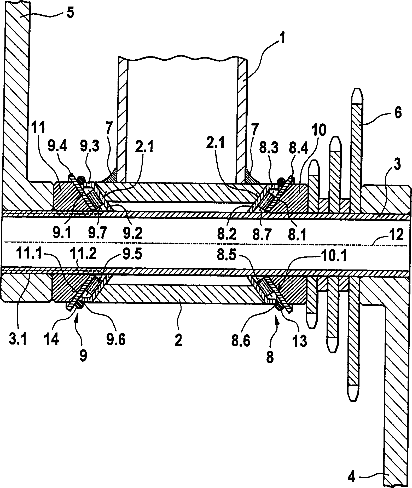
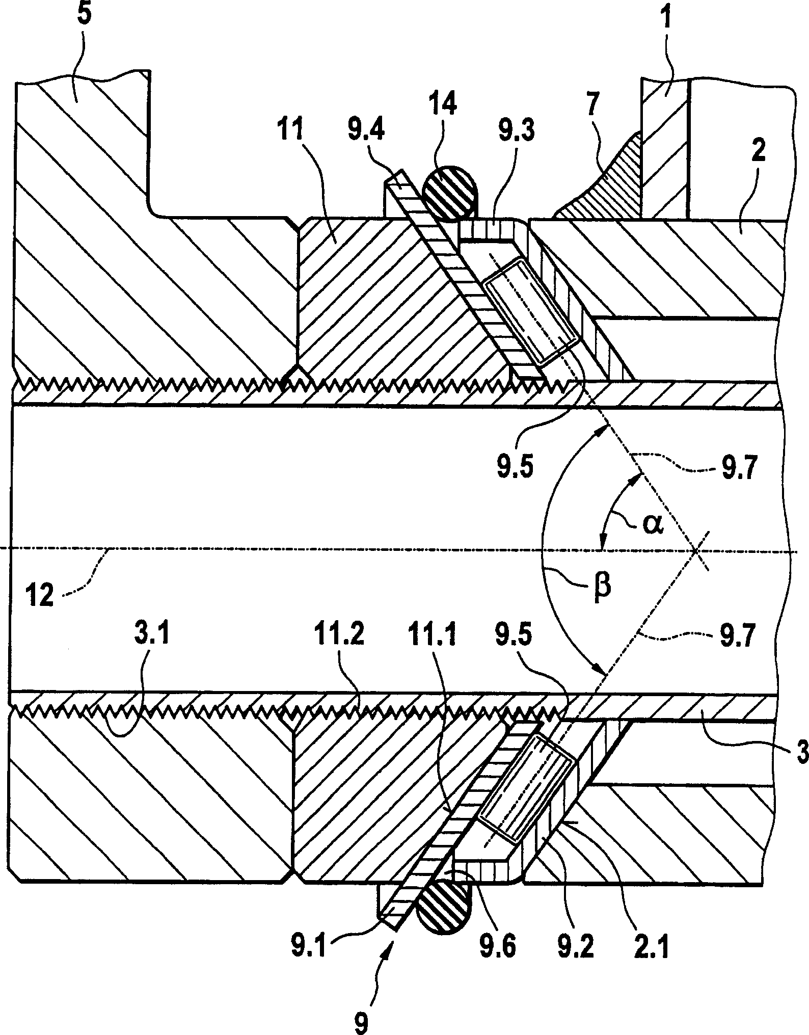
[0021] exist figure 1 and 2 The pedal bearing unit for a bicycle shown schematically in , consists of a pedal bearing shaft 3 configured as a hollow shaft, which is connected on both sides to the pedals 4 and 5 and is accommodated by the pedal bearing housing 2 , the pedal bearing shell is connected with the vehicle frame 1 through the welding seam 7 again. The rotatable accommodation of the pedal bearing shaft 3 in the housing 2 takes place via two axially inclined needle bearings 8 , 9 spaced apart from one another in the axial direction. The two needle roller bearings have needle rollers 8.5, 9.5 whose axes of rotation 8.7, 9.7 are arranged obliquely at an angle α to the bearing axis 12, wherein the needle rollers 8.5, 9.5 can be arranged in a cage, which is shown in the figure not shown. The outer turntables 8.1, 9.1 and the inner turntables 8.2, 9.2 belong to each bearing 8, 9, and these turntables rest on conical bearing surfaces 2.1, 10.1, 11.1, which are respectivel...


PUM


Abstract

The pedal bearing unit has a pedal bearing axle (3) connected to the pedal cranks (4,5) and housed rotatable in a housing (2) through two spaced rolling bearings formed as axial inclined needle bearings (8,9) whose bearing needles (8.5, 9.5) have rotary axles (8.7, 9.7) which roll at an angle inclined to a bearing axle on associated tracks between two flat metal washer disc (8.1,8.2, 9.1,9.2). The inclined needle bearings are tensioned against one another through conical contact bearing faces (2.1, 10.1, 11.1) The flat washer discs are made through chipless shaping and subjected to a hardening process.

Description

technical field [0001] The invention relates to a pedal bearing unit (Tretlagereinheit), especially for bicycles, comprising a pedal bearing shaft connected to the pedals, which is rotatably accommodated in a vehicle frame via two mutually spaced rolling bearings in the attached pedal bearing housing. Background technique [0002] Such a pedal bearing unit is known, for example, from DE 82 30 552 U1, wherein the bearing is arranged in a bush inserted into the coupling of the bicycle frame and the bush is screwed into the coupling of the frame For axial and radial fixation. The bearing is configured as a deep groove ball bearing, wherein at least one ball raceway is formed in the bushing. One such pedal bearing unit is fixed as a whole in the frame coupling. [0003] Another pedal bearing arrangement is known from DE 298 11 216 U1. In this arrangement, the two screw caps are each screwed into mutually opposing internal threads of the bearing housing of the pedal bearing. ...

Claims


Application Information

Patent Timeline
Patent Type & Authority Applications(China)
IPC IPC(8): B62M1/02F16C19/44B62M1/36
CPCF16C33/78B62M3/003F16C19/36F16C25/06F16C33/588F16C19/54F16C19/361F16C19/46F16C19/548F16C2326/28
Inventor 马蒂亚斯·施佩伯
Owner INA SCHAEFFLER KG
Why Eureka
Try Eureka