
Card mounting device

A technology for mounting devices and mounting parts, which is applied in the direction of coupling devices, cooperative devices, components of connecting devices, etc., which can solve problems such as thinning obstacles and achieve the effect of protecting circuits

Inactive Publication Date: 2006-12-20
ALPS ALPINE CO LTD
View PDF2 Cites 0 Cited by
  • Summary
  • Abstract
  • Description
  • Claims
  • Application Information

AI Technical Summary

Problems solved by technology

Conventionally, even if a chip resistor considered as a resistor is used, the thickness of the terminal is increased by at least about 1 mm, which is an obstacle to thinning

Method used


Image

  • Card mounting device
  • Card mounting device
  • Card mounting device

Examples


Embodiment Construction

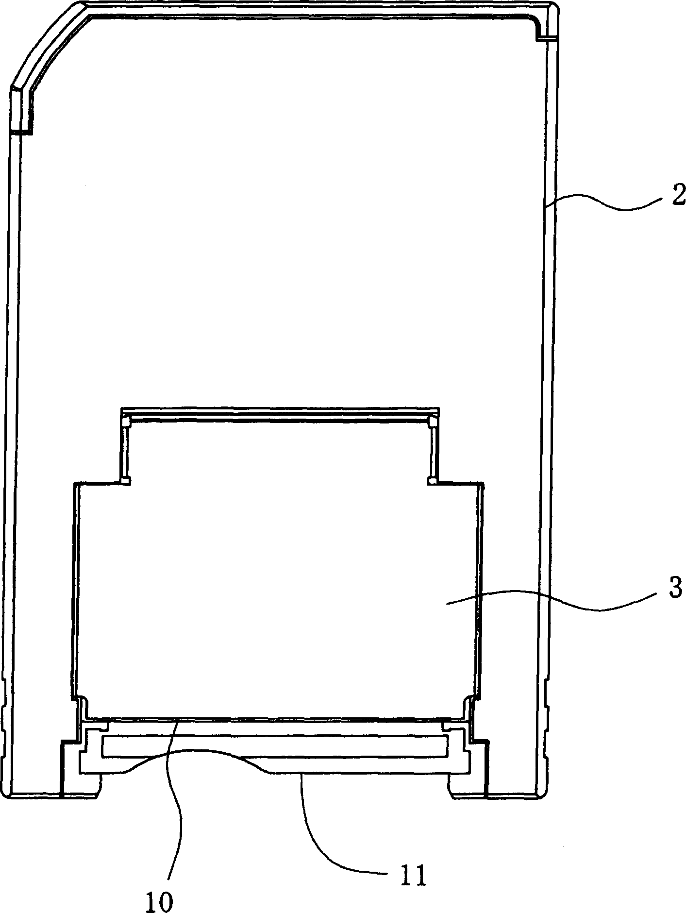
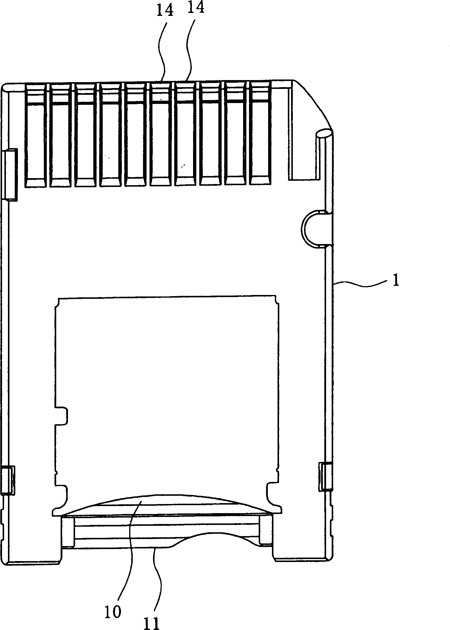
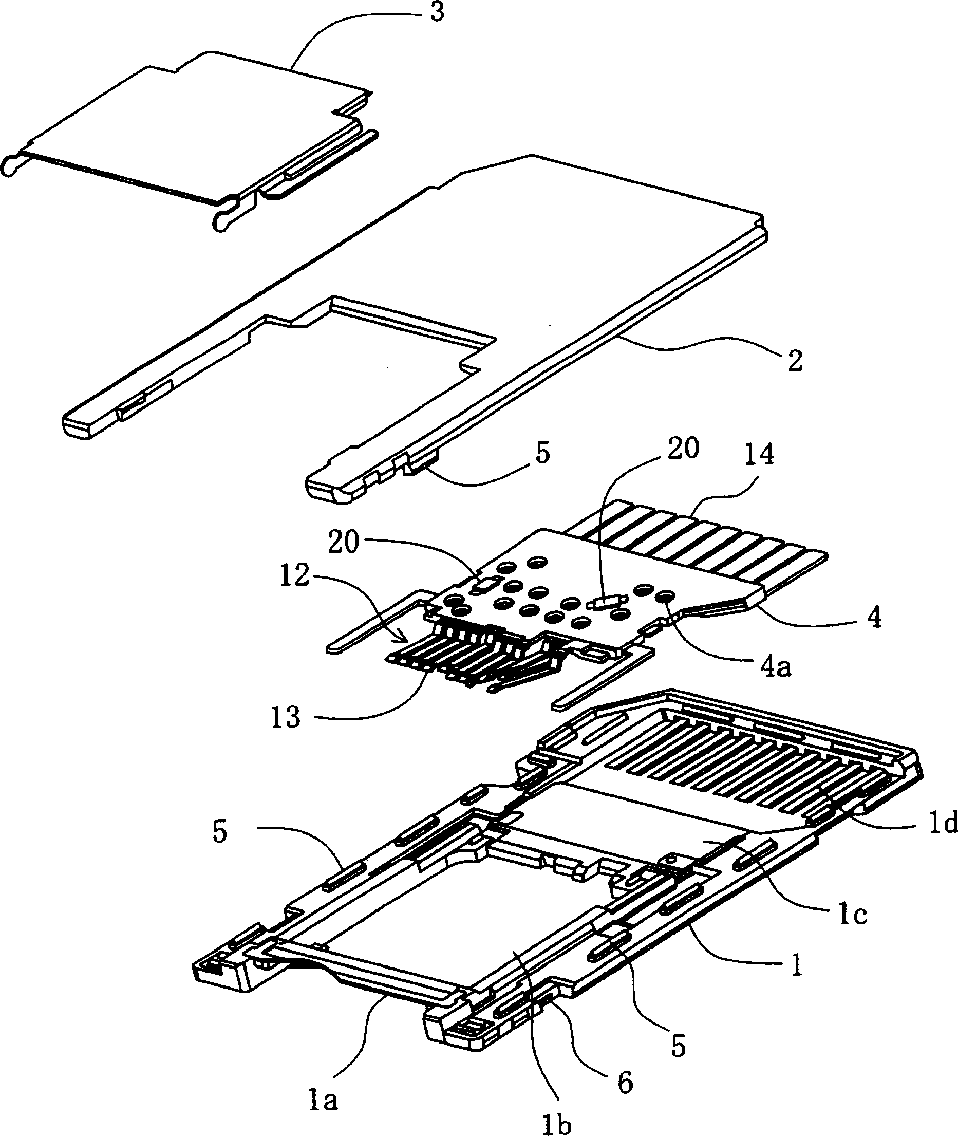
[0027] Embodiments of the present invention will be described in detail with reference to the drawings. In this embodiment, a card adapter is shown as a card mounting device. figure 1 It is a plan view of the card adapter of this embodiment, figure 2 is the bottom view of the card adapter. in addition, image 3 is an exploded oblique view of the card adapter. The card adapter of this embodiment is configured to be able to mount a small card, has the same size as a large card, and can be mounted to a card connector for reading and writing signals.

[0028] like figure 1 As shown, an insertion port 11 for inserting a small card is formed at the rear of the card adapter. In addition, the inside of the card adapter is formed in a hollow shape, and constitutes a mounting portion 10 capable of mounting a small card. and, if figure 2 As shown, a plurality of connector-side terminals 14, 14 for electrical connection with the card connector are provided on the front of the car...


PUM


Abstract

A card mounting device is provided to form a very thin resistor by inserting the resistor in an intermediate position of at least one of terminals for a card and forming the resistor by printing, thereby inserting the resistor without significantly increasing the thickness of the terminal for the card, and contributing to sliming as installing the resistor. In a card mounting device having a mounting unit capable of mounting a card having an external connector, and plural terminals(13) for the card in which a side of its end is exposed to the mounting unit and which are connected with the external connector of the card, a resistor(20) is inserted between both ends of at least one of terminals(13) for each card. The resistor(20) is formed by printing.

Description

technical field [0001] The present invention relates to a card mounting device capable of mounting a card used as a memory card, and more particularly to a card mounting position capable of removing noise from a signal from the card and protecting a circuit. Background technique [0002] A compact card equipped with a storage function and the like is widely used in digital cameras, mobile phones, and the like. In order to read and write information stored in the compact card, a card connector capable of mounting the card is required. As such a card connector, for example, a device disclosed in Patent Document 1 is used. [0003] In addition, the above-mentioned cards have different sizes, and a card adapter for installing a small card is also used, so that the small card can be installed to the card connector of a large card. As such a card adapter, for example, a device disclosed in Patent Document 2 is used. These card connectors and card adapters are collectively refer...

Claims


Application Information

Patent Timeline
IPC IPC(8): H01R12/16H01R13/66H05K1/16G06K17/00
CPCG06K7/0056G06K19/07732H01R12/71H01R13/2442H01R13/629
Inventor 佐藤一树我妻透川端隆志
Owner ALPS ALPINE CO LTD
Learn More