Motor and connector for semiconductor

A motor and permanent magnet technology, applied in the field of motors, can solve the problem of uneven distribution of reluctance, and achieve the effects of substantially uniform reluctance, increased effective magnetic flux, and increased output

Inactive Publication Date: 2006-12-20
KK TOSHIBA
View PDF1 Cites 15 Cited by
  • Summary
  • Abstract
  • Description
  • Claims
  • Application Information

AI Technical Summary

Problems solved by technology

Therefore, there is a problem that the reluctance of the joining portion of the yoke portion 1 and the tooth portion 2 is unevenly distributed in the axial and circumferential directions.

Method used


Image

  • Motor and connector for semiconductor
  • Motor and connector for semiconductor
  • Motor and connector for semiconductor

Examples


no. 3 example 1

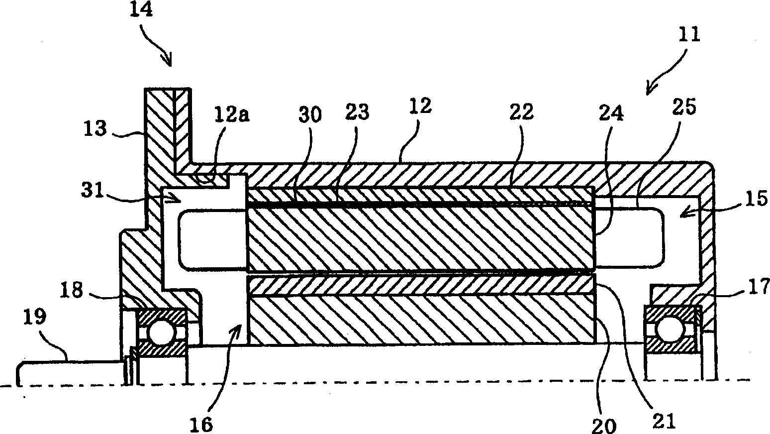
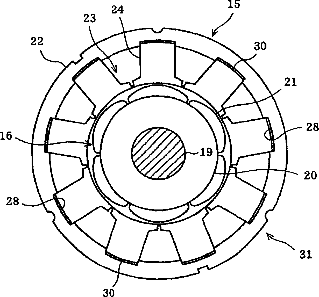
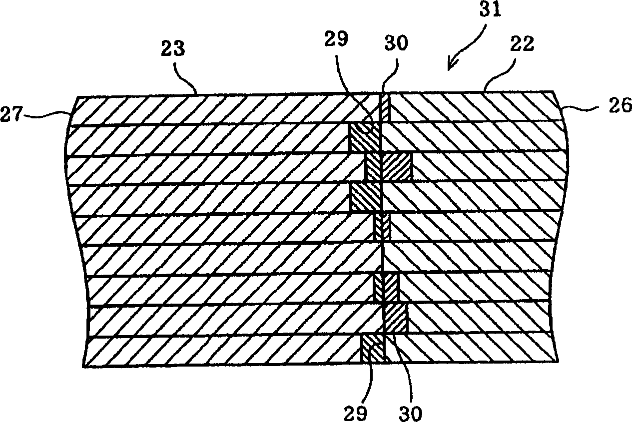
[0082] As in the third embodiment, the assembly jig 44 is also used to manufacture the stator 15 in the fifth embodiment. That is, the stator winding 25 is wound on each tooth 42, and the compound 30 is applied or sprayed on both end surfaces 43a of each split iron core 41, and then the inner peripheral end surfaces 42a of the nine teeth 42 are crimped to the mounting jig 44. on the outer peripheral surface 44a. As a result, the plurality of sawtooth-shaped fine unevenness portions 71 on both end surfaces 43 a of adjacent split cores 41 mesh with each other. In this state, split core 41 is pressurized from outer peripheral surface 43 . As a result, the plurality of saw-tooth-shaped fine unevenness portions 71 are crushed, and the joined portions of the split cores 41 are brought into close contact.

[0083] Thereby, the gap between the split iron cores 41 can be made extremely small, and the jiggle torque can be further reduced.

[0084] Figure 13 Shown is the sixth embod...


PUM


Abstract

An electric motor includes a stator including a stator core made of a plurality of split cores joined to each other and a stator winding wound on the stator core, and an admixture interposed in a joint between the split cores and comprising a binder mixed with a granular magnetic substance.

Description

technical field [0001] The present invention relates to a motor in which a stator core is formed by joining a plurality of divided iron cores, and more particularly to a motor in which the divided iron core is formed by laminating a plurality of stamped steel plates, and a connection device for semiconductors such as a connector using the motor. Background technique [0002] Conventionally, there is known a technique in which a stator core is formed by joining a plurality of split cores, and the split core is formed of laminated steel plates (for example, refer to Patent Document 1). [0003] Figure 16 Shown are a stator core 3 formed by joining an annular tooth portion 2 to the inner peripheral portion of an annular yoke portion 1 , and a rotor 4 disposed on the inner periphery of the stator core 3 . The rotor 4 is composed of a rotor core 5 and a plurality of permanent magnets 6 arranged on the outer periphery thereof. Both the yoke 1 and the teeth 2 are formed by stacki...

Claims


Application Information

Patent Timeline
Patent Type & Authority Applications(China)
IPC IPC(8): H02K1/12H02K3/04H02K15/02
Inventor 永田正人黑田昌宽横山光之串平孝信中山忠宏篠原刚
Owner KK TOSHIBA
Why Eureka
Try Eureka