stator and motor

A stator and stator slot technology, applied in the direction of electromechanical devices, electrical components, electric components, etc., can solve the problems of reducing motor efficiency, affecting the effective power of the motor, interference, etc., and achieve the goal of improving motor efficiency, reducing vibration and noise, and reducing magnetic flux leakage Effect

Active Publication Date: 2022-05-13
ZHUHAI GREE REFRIGERATION TECH CENT OF ENERGY SAVING & ENVIRONMENTAL PROTECTION
View PDF0 Cites 0 Cited by
  • Summary
  • Abstract
  • Description
  • Claims
  • Application Information

AI Technical Summary

Problems solved by technology

[0002] In the existing motor industry, motors with stator excitation structures all generate positive-rotating magnetic fields, and the excitation windings are distributed according to the requirements for generating positive-rotating magnetic fields, so that the excitation magnetic field forms a magnetic field waveform that is approximately positive-rotating along the pole surface. When the winding has an excitation current, a magnetic field will be generated on the surface of the magnetic pole surrounded by the winding, that is, the magnetic force line will pass through, and the magnetic force line generated by the winding will propagate in the motor through the stator core and the rotor core, but not all the magnetic force lines can Propagated according to the preset route, some of the magnetic field lines form a small-scale closed loop around the excitation magnetic field, generating some harmonics, which have certain interference to the sine wave generated by the main magnetic field of the motor, which will affect the effective power of the motor , reducing the motor efficiency

Method used


Image

  • stator and motor
  • stator and motor
  • stator and motor

Examples


Embodiment 1

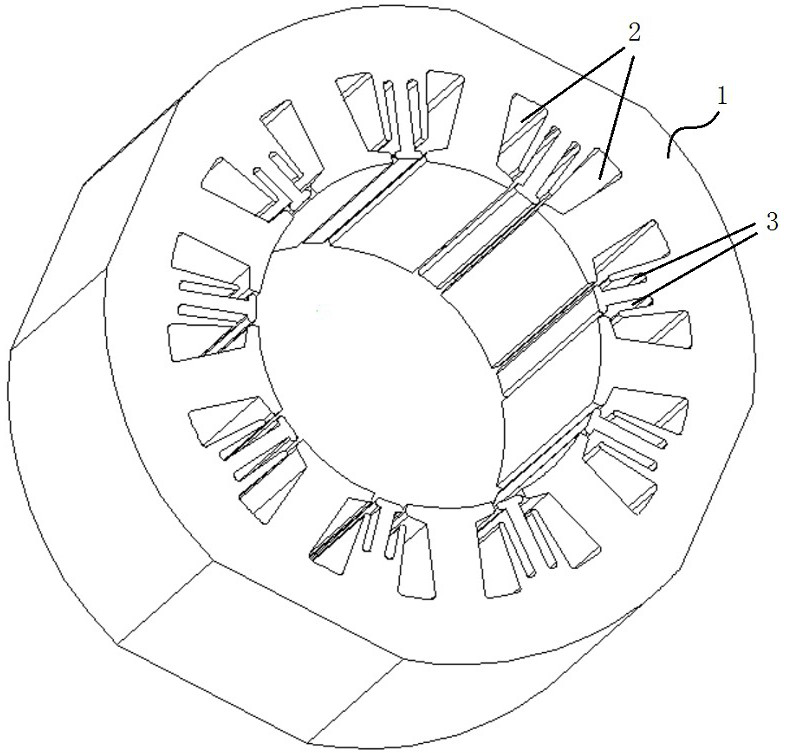
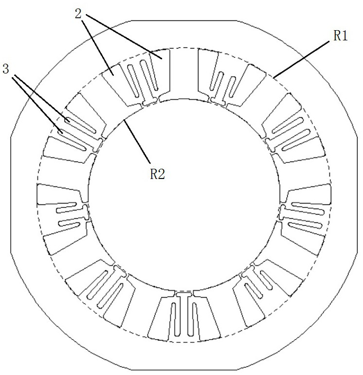
[0031] Such as Figure 1-2 As shown in , this embodiment provides a stator 1 that is provided with two magnetic isolation cavities 3 between two adjacent stator slots 2 . The magnetic isolation cavity 3 axially penetrates the two end faces of the stator 1 on the stator 1 . The magnetic isolation chamber 3 is arranged between two adjacent stator slots 2, close to the excitation winding, and two magnetic isolation chambers 3 are distributed on both sides of the magnetic pole centerline of the two adjacent stator slots 2, thereby hindering the leakage flux. produce. The magnetic isolation cavity 3 communicates with the adjacent stator slot 2 to form a through slot, which is equivalent to forming a relatively large magnetic resistance and hindering the formation of magnetic flux leakage lines.

[0032] In this embodiment, the structures of the magnetic isolation cavities 3 on the stator 1 are uniform, and the cross-section of the magnetic isolation cavity 3 is a rectangle with r...

Embodiment 2

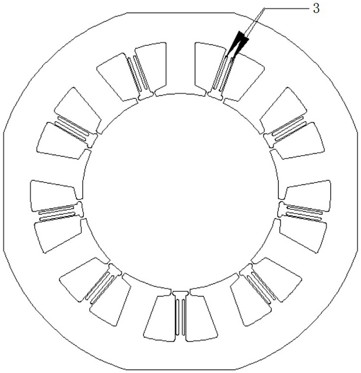
[0035] Such as image 3 As shown in , this embodiment provides a stator 1 that is provided with two magnetic isolation cavities 3 between two adjacent stator slots 2 . The magnetic isolation cavity 3 axially penetrates the two end faces of the stator 1 on the stator 1 . The magnetic isolation chamber 3 is arranged between two adjacent stator slots 2, close to the excitation winding, and two magnetic isolation chambers 3 are distributed on both sides of the magnetic pole centerline of the two adjacent stator slots 2, thereby hindering the leakage flux. produce. There is no communication between the magnetic isolation cavity 3 and the adjacent stator slot 2, so as to prevent the excessive motor reluctance torque from causing high requirements on the mechanical strength of the motor.

[0036] In this embodiment, the structures of the magnetic isolation cavities 3 on the stator 1 are uniform, and the cross section of the magnetic isolation cavity 3 is rectangular.

Embodiment 3

[0038] Such as Figure 4 As shown in , this embodiment provides a stator 1 that is provided with two magnetic isolation cavities 3 between two adjacent stator slots 2 . The magnetic isolation cavity 3 axially penetrates the two end faces of the stator 1 on the stator 1 . Two magnetic isolation cavities 3 are arranged between two adjacent stator slots 2, close to the field winding. The cross sections of the two magnetic isolation cavities 3 are oval, but the widths of the two magnetic isolation cavities 3 are different. The two magnetic isolation cavities 3 are arranged along the pole centerlines of the two adjacent stator slots 2, so as to prevent the generation of magnetic leakage flux. The two magnetic isolation cavities 3 are not connected to the stator slot 2, so as to prevent the excessive motor reluctance torque from causing higher mechanical strength requirements of the motor.


PUM


Abstract

The invention relates to a stator, which includes a stator slot, and no less than two magnetic isolation cavities are arranged between two adjacent stator slots, and the magnetic isolation cavity penetrates two end faces of the stator in the axial direction. The present invention also relates to an electrical machine provided with the above-mentioned stator.

Description

technical field [0001] The invention relates to the field of motors, in particular to a stator and a motor using the stator. Background technique [0002] In the existing motor industry, motors with stator excitation structures all generate positive-rotating magnetic fields, and the excitation windings are distributed according to the requirements for generating positive-rotating magnetic fields, so that the excitation magnetic field forms a magnetic field waveform that is approximately positive-rotating along the pole surface. When the winding has an exciting current, a magnetic field will be generated on the surface of the magnetic pole surrounded by the winding, that is, the magnetic force line will pass through, and the magnetic force line generated by the winding will propagate in the motor through the stator core and the rotor core, but not all the magnetic force lines can Propagated according to the preset route, some of the magnetic field lines form a small-scale clo...

Claims


Application Information

Patent Timeline
Patent Type & Authority Patents(China)
IPC IPC(8): H02K1/12H02K1/14H02K11/01
CPCH02K1/12H02K1/146H02K11/01H02K2213/03
Inventor 张继胤江胜军张强龙芳李尚平
Owner ZHUHAI GREE REFRIGERATION TECH CENT OF ENERGY SAVING & ENVIRONMENTAL PROTECTION
Why Eureka
Try Eureka