Die unit and injection forming machine

A technology for injection molding machines and molds, applied in the field of mold units and injection molding machines using sliding positioners, can solve the problems of loss of precision of mold unit 100, unfavorable positioning of molds 102 and 104, etc., and reduce wear and contact area Small, wear-reducing effect

Inactive Publication Date: 2006-12-27
ASIA OPTICAL CO INC
View PDF0 Cites 0 Cited by
  • Summary
  • Abstract
  • Description
  • Claims
  • Application Information

AI Technical Summary

Problems solved by technology

However, the mold unit 100 will tilt or deviate due to the gap between the guide pin 110 and the guide sleeve 120 when the mold is closed (that is, the molds 102 and 104 are closed), which is not conducive to the positioning between the molds 102 and 104
In addition, when the molds 102 and 104 of the mold unit 100 are opened and closed for a long time, the guide pin 110 and the guide sleeve 120 will contact and collide again and again to cause surface wear, resulting in loss of precision of the mold unit 100

Method used


Image

  • Die unit and injection forming machine
  • Die unit and injection forming machine
  • Die unit and injection forming machine

Examples


Embodiment Construction

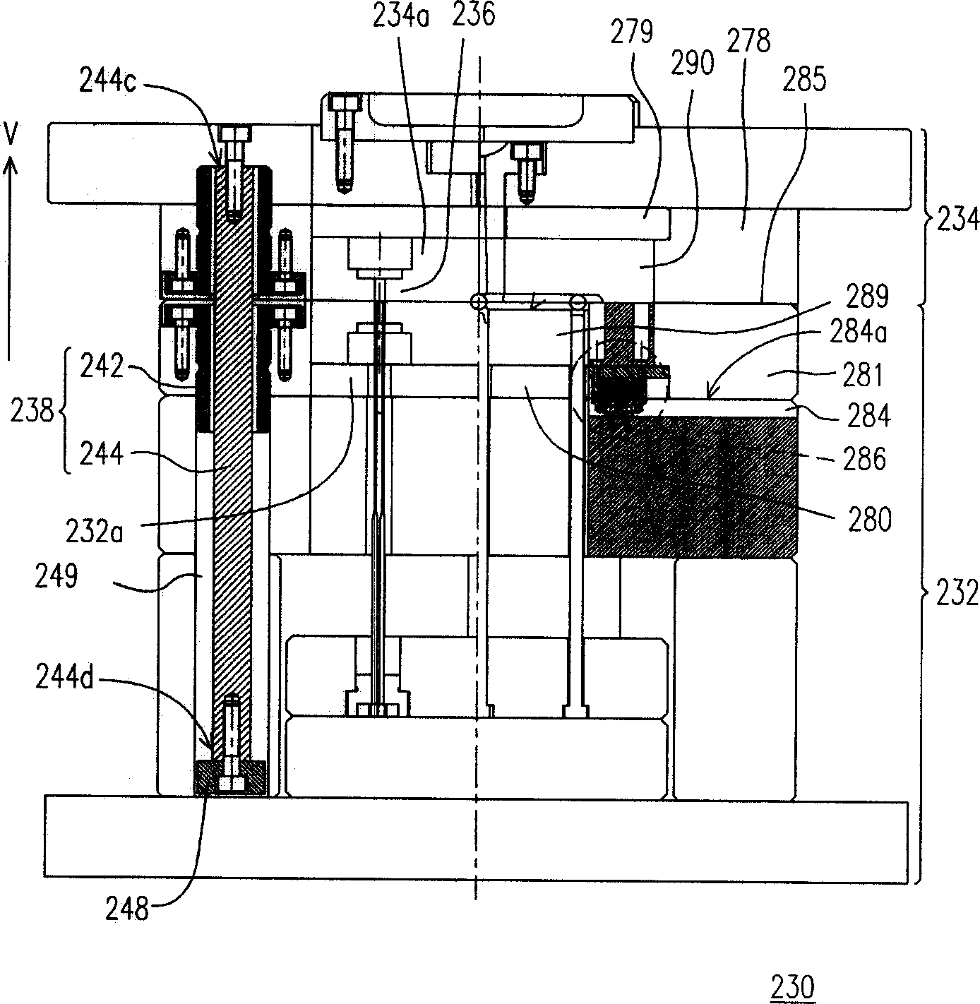
[0076] Figure 3A ~ Figure 3C It is a schematic diagram of a mold unit according to an embodiment of the present invention. in, Figure 3A is the front view of the die unit, Figure 3B is the bottom view of the second member of the mold unit, and Figure 3C is a top view of the first member of the mold unit.

[0077] Please refer to Figure 3A ~ Figure 3C , the mold unit 230 includes a first member 232, a second member 234, at least one slide positioner 286 (four in this embodiment), at least one guide pin 282 (four in this embodiment), and at least one Guide sleeves 283 (4 in this embodiment). Wherein, the first component 232 includes a carrier plate 284 , a first back plate 280 , a first insert 289 , a first mold plate 281 and a first mold core 232 a. The first mold core 232a is disposed on the first insert 289, and the first insert 289 and the first back plate 280 move relative to the support plate 284 on the two-dimensional plane 284a. The second member 234 is dispo...


PUM


Abstract

One kind of mold unit and injection molding machine. The mold unit consists of the first member, the second member, at least one sliding localizer, at least one guide pin and at least one guide sleeve. Of them, the first member contains the cavity retainer plate, the first back plate, the first insert and the first cavity. The first insert is fixed onto the first back plate. The first cavity is placed in the hole in the cavity of the first insert and can perform relative 2D movements against the cavity retainer plate. The second member is located on the opposite of the first member, with the second cavity being fixed on the second insert and a cavity being formed between the first cavity and the second cavity. The sliding localizer is equipped between the cavity retainer plate and the first back plate, so the first cavity can be at a desired 2D position in respect of the supporting plate. What's more, the guiding pin is on either the first cavity or the second cavity and the guiding sleeve is on the other cavity.

Description

technical field [0001] The present invention relates to a mold unit and an injection molding machine, and in particular to a mold unit and an injection molding machine using a sliding positioner. Background technique [0002] In recent years, with the advancement of science and technology, various optical products including cameras, digital cameras, camcorders, digital video cameras, fax machines, copiers, CD players, scanners and projectors, etc., have continued to improve in performance and drop in price. It has gradually become popular in daily life. [0003] General optical products have precision optical lenses, which are mainly composed of two spherical mirrors or aspheric mirrors. If the optical axis passes through the centers of the two mirrors without deviation, better image quality can be obtained. At present, the molding methods of optical lenses mainly include grinding and molding. [0004] Injection molding machines are commonly used tools when making optical ...

Claims


Application Information

Patent Timeline
Patent Type & Authority Applications(China)
IPC IPC(8): B29C45/26B29C45/03
Inventor 赵圣瑞余忠道
Owner ASIA OPTICAL CO INC
Why Eureka
Try Eureka