

Transverse magnetic field permanent-magnet synchronous motor with rotor magnetic pole three-sided wall type structure
A permanent magnet synchronous motor, transverse magnetic field technology, applied in the synchronous motor with static armature and rotating magnet, magnetic circuit shape/pattern/structure, winding conductor shape/pattern/structure and other directions, can solve the complex stator structure and other problems, to achieve the effect of increasing the air gap magnetic density and improving the performance
- Summary
- Abstract
- Description
- Claims
- Application Information
AI Technical Summary
Problems solved by technology
Method used
Image

Examples
Embodiment Construction
[0014] The invention proposes a transverse magnetic field permanent magnet synchronous motor with a rotor magnetic pole three-wall structure, which is proposed to solve the complicated stator structure in the existing magnetic concentration type transverse magnetic field permanent magnet motor. The present invention will be described below in conjunction with the accompanying drawings.
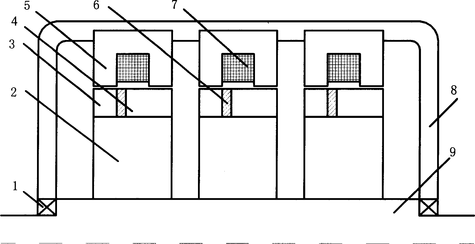
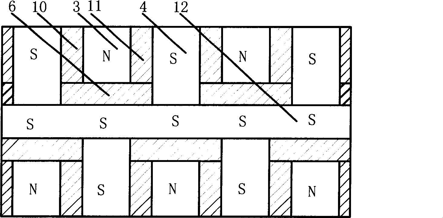
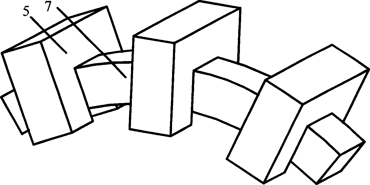
[0015] figure 1 Including U-shaped stator core 5, annular stator winding 7, three-wall rotor permanent magnet poles 6, 10, 11; rotor cores 3, 4, 12, rotor bracket 2, rotating shaft 9, bearing 1. The stator 5 is made of U-shaped silicon steel sheets, forming a U-shaped iron core with the same number of pole pairs as the motor, which is evenly distributed along the circumference and fixed on the casing 8; the stator winding 7 is a ring coil structure, placed in the stator U-shaped The bottom of the core slot (such as image 3 shown); each phase of the rotor has two magnetic pole rings, and the...
PUM
 Abstract
Description
Claims
Application Information