Rotating connection apparatus for borehole pump pouring concrete rotary guniting enlarging footing piling

A technology of concrete rotary spraying grouting and rotary joints, which is applied in the pile-forming device of pressure grouting and in the field of pressure grouting for construction, and can solve problems such as increasing production costs, grout leakage at the grout inlet, and affecting grouting speed and quality. It achieves the effects of easy disassembly, improved single-column bearing capacity, and good work quality

Inactive Publication Date: 2007-01-03
刘润郊
View PDF1 Cites 4 Cited by
  • Summary
  • Abstract
  • Description
  • Claims
  • Application Information

AI Technical Summary

Problems solved by technology

[0003] The purpose of the present invention is to solve the existing pile-forming device for pouring large flow concrete with swirling jet slurry, because there is no retaining ring installed between the top of the jacket and the upper connection plate, and the bearing adopts an ordinary ball bearing, which may cause problems during operation. The casing moves upwards, resulting in grout leakage at the grouting port, which affects the grouting speed and quality, and increases the production cost. A rotary joint device used for drilling pump grouting with rotary jet grouting and expanding bottom to form piles

Method used


Image

  • Rotating connection apparatus for borehole pump pouring concrete rotary guniting enlarging footing piling
  • Rotating connection apparatus for borehole pump pouring concrete rotary guniting enlarging footing piling

Examples


specific Embodiment approach 1

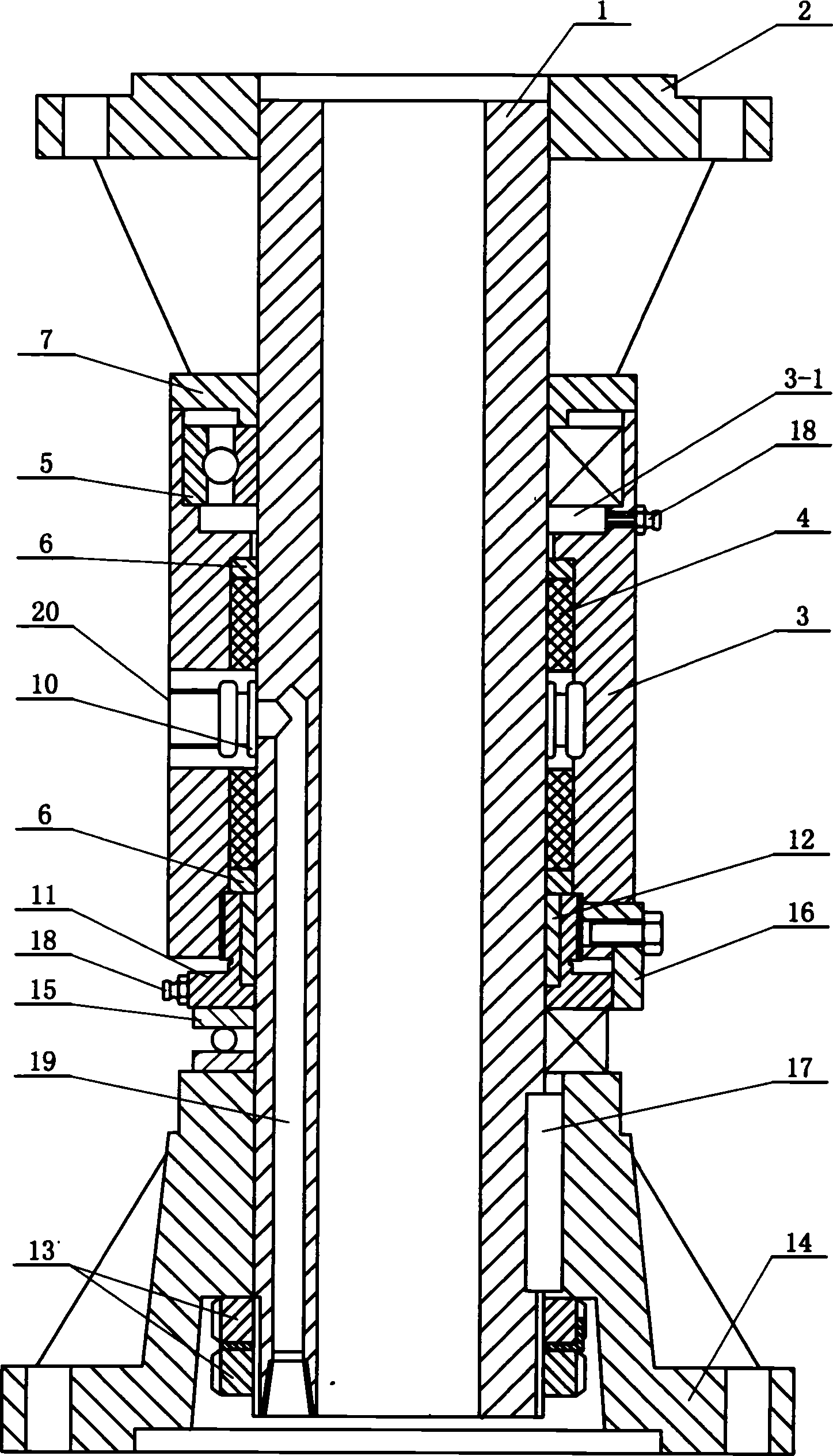
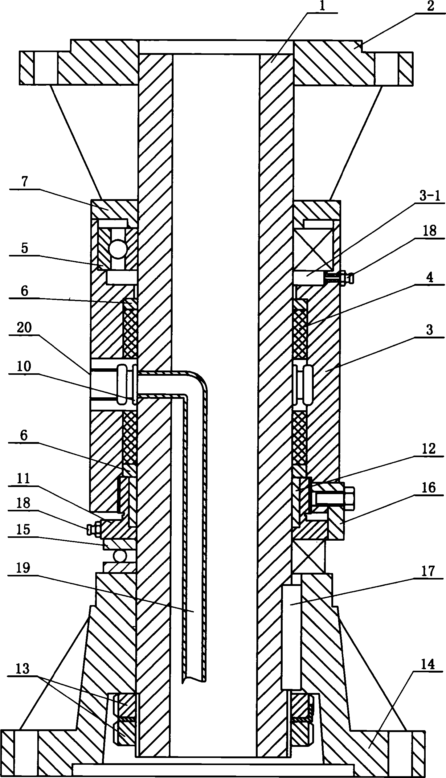
[0006] Specific implementation mode one: combine figure 1 , figure 2 Describe this embodiment, this embodiment consists of a main body pipe 1, an upper connecting plate 2, an outer jacket 3, a sealing sleeve 4, a first bearing 5, a retaining ring 7, a flower sleeve 10, a lower connecting plate 14, a second bearing 15, a slurry Pipe 19 and slurry inlet hole 20; the upper end of the main pipe 1 is fixed in the upper connection plate 2, the lower end of the main pipe 1 is fixed in the lower connection plate 14, the main pipe 1 is equipped with a jacket 3, the main pipe 1 and the jacket 3 Sealing sleeve 4 is housed between, outer jacket 3 and main body pipe 1 are provided with grouting hole 20 along the radially corresponding position, and flower cover 10 is housed on the main body pipe 1 in the grouting hole 20, the inside end of grouting hole 20 and The upper end of the slurry delivery pipe 19 is connected, the main body pipe 1 between the first bearing 5 and the upper connect...

specific Embodiment approach 2

[0007] Specific implementation mode two: combination figure 1 , figure 2 Describe this embodiment, the difference between this embodiment and specific embodiment one is: this embodiment also adds lubricating device 18; on the side wall. The lubricating device 18 is added to lubricate the first bearing 5 and the second bearing 15 respectively, ensuring that the first bearing 5 and the second bearing 15 work in a lubricated state, and prolonging the use of the first bearing 5 and the second bearing 15 life.

specific Embodiment approach 3

[0008] Specific implementation mode three: combination figure 1 , figure 2 Describe this embodiment, the difference between this embodiment and the specific embodiment one is: this embodiment also adds a pressure ring 11, a copper sleeve 12, and a retaining key 16; A copper sleeve 12 is installed between the ring 11 and the main pipe 1 , and a retaining key 16 is fixed on the outer end of the pressure ring 11 . A copper sleeve 12 is installed between the pressure ring 11 and the main pipe 1, which can not only support the sealing sleeve 4, but also reduce the friction between the jacket 3 and the main pipe 1, so that the whole device does not generate heat when it is working. Resistant to wear, thereby increasing the service life of the entire unit.


PUM


Abstract

The present invention relates to a building pile-forming equipment by pressure injecting concrete and pressure injecting cement slurry. Said invention is characterized by that said pile-forming equipment includes a min body pipe, its upper end and lower end are respectively fixedly mounted in upper connecting disk interior and lower connecting disk interior, on the main body pipe a case shell is mounted, on the case shell and main body pipe are set several slurry-feeding holes connected with slurry-conveying pipe. In the case shell a first bearing is mounted, the upper end of said first bearing is equipped with a baffle ring, a second bearing is mounted on the main body pipe of upper end of lower connecting disk, said second bearing adopts angular contact bearing.

Description

Technical field: [0001] The invention relates to a pile-forming device for pressure-grouting concrete and pressure-grouting grout for construction, in particular to a rotary joint device for pile-forming by drilling pump grouting concrete and rotary spraying grout to expand the bottom. Background technique: [0002] At present, people have developed a variety of concrete pile forming methods and pile forming devices under weak geological conditions and high water level geological conditions around the modern construction machinery of concrete delivery pumps. In 2003, I applied for a utility model patent related to "drilling pump pouring large flow concrete rotary jet grouting piling device", the patent number is ZL03211035.9. After several years of practice in this utility model patent, it is found that there are following problems in the structural design, that is, because there is no retaining ring installed between the top of the jacket and the upper connection plate, and...

Claims


Application Information

Patent Timeline
Patent Type & Authority Applications(China)
IPC IPC(8): E02D5/44E02D15/04
Inventor 刘润郊
Owner 刘润郊
Why Eureka
Try Eureka