Supercharge Your Innovation With Domain-Expert AI Agents!

X-ray CT apparatus

A technology of X-rays and X-ray tubes, applied in the field of multi-tube X-ray CT devices and filters

Inactive Publication Date: 2007-01-10
KK TOSHIBA +1
View PDF2 Cites 4 Cited by
  • Summary
  • Abstract
  • Description
  • Claims
  • Application Information

AI Technical Summary

Problems solved by technology

[0005] However, there is a problem with the multi-tube type X-ray CT apparatus that if Figure 4 As shown, the scattered rays formed by the X-rays generated by a pair of X-ray tubes 122 (121) are detected by another pair of X-ray detectors 131 (132)

Method used


Image

  • X-ray CT apparatus
  • X-ray CT apparatus
  • X-ray CT apparatus

Examples


Embodiment Construction

[0032] Hereinafter, an embodiment of the present invention will be described in detail with reference to the drawings.

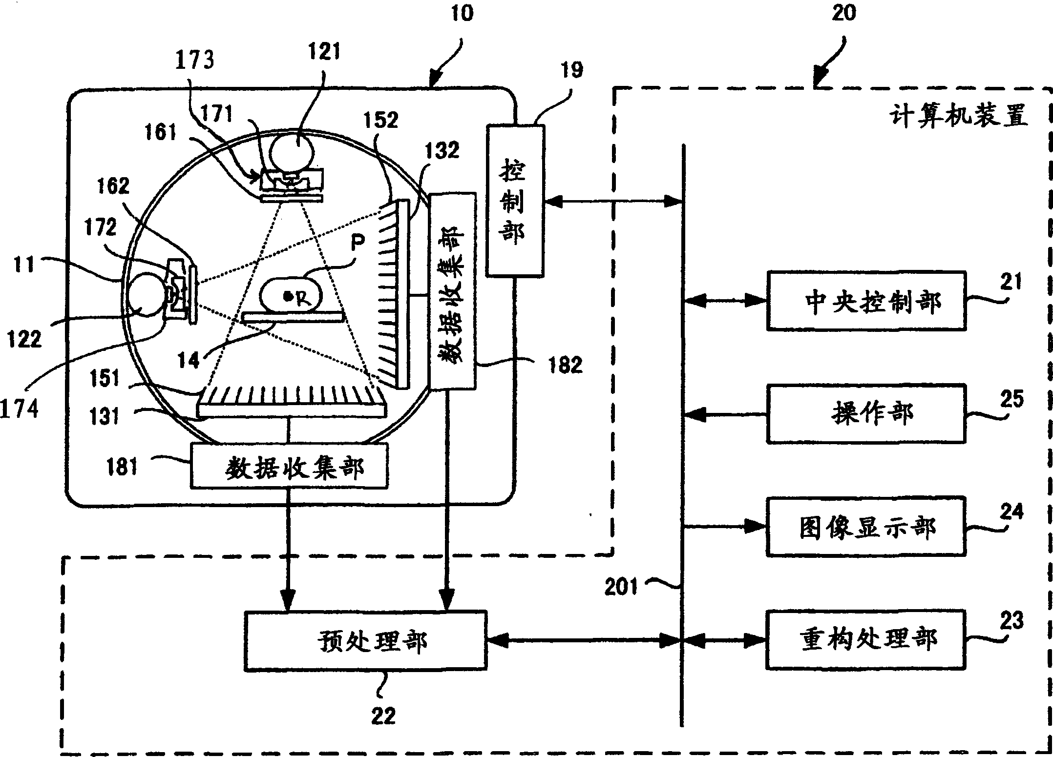
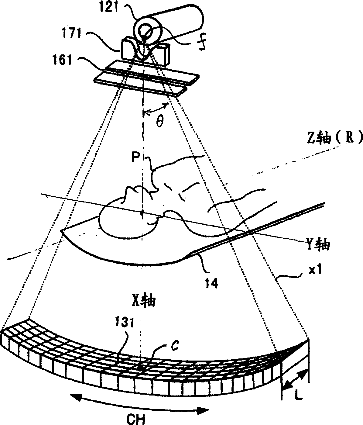
[0033] figure 1 It is a configuration diagram showing the overall configuration of an embodiment of the X-ray CT apparatus of the present invention. exist figure 1 Among them, the X-ray CT apparatus (X-ray computerized tomography apparatus) of this embodiment has a gantry 10, a computer device 21, and a bed (not shown). The gantry 10 is a multi-tube type, and a plurality of scanners including pairs of X-ray tubes and X-ray detectors are mounted. In this embodiment, it demonstrates as a 2-tube ball type.

[0034] A rotating base 11 is provided on the pallet 10 . The rotating base 11 is rotated around the rotating axis R by a rotating mechanism. The scanning system composed of the first pair of X-ray tube 121 and X-ray detector 131 and the second pair of X-ray tube 122 and X-ray detector 132 is arranged at a predetermined angle (for example, 90 degrees)...


PUM


Abstract

An X-ray CT apparatus includes a plurality of X-ray tubes, a plurality of X-ray detectors corresponding to the plurality of X-ray tubes, respectively, a support mechanism which supports the X-ray tubes and the X-ray detectors to allow the X-ray tubes and the X-ray detectors to rotate about a single rotation axis, a reconstruction unit which reconstructs image data on the basis of outputs from the X-ray detectors, and a plurality of filters which are respectively provided for the plurality of X-ray tubes and each have a characteristic in which an X-ray path length changes along a curve approximate to an inverted Gaussian curve from the rotation center to the two ends of an X-ray beam.

Description

[0001] Cross References to Related Applications [0002] This application is based upon and claims the benefit of priority from prior Japanese Patent Application No. 2005-191922 filed on June 30, 2005, the entire contents of which are incorporated herein by reference. technical field [0003] The present invention relates to a multi-tube type X-ray CT apparatus equipped with a plurality of pairs of X-ray tubes and detectors and a filter. Background technique [0004] An X-ray CT apparatus (X-ray computerized tomography apparatus) reconstructs a tomographic image from a plurality of projection data sets collected from a plurality of directions by rotating a pair consisting of an X-ray tube and a detector. A multi-tube type X-ray CT apparatus is equipped with a plurality of the above pairs. A multi-tube type X-ray CT apparatus is described, for example, in JP-A-2004-73406. Japanese Patent Laid-Open No. 2004-73406 includes an X-ray tube for treatment and an X-ray tube for dat...

Claims


Application Information

Patent Timeline
IPC IPC(8): A61B6/03A61N5/10G21K1/04
CPCA61B6/583H05G1/70G01N23/046G01N2223/419G01N2223/612
Inventor 松田圭史
Owner KK TOSHIBA
Features
  • R&D
  • Intellectual Property
  • Life Sciences
  • Materials
  • Tech Scout
  • Unparalleled Data Quality
  • Higher Quality Content
  • 60% Fewer Hallucinations
Learn More