Plate glass transferring device

A flat glass and conveying device technology, used in glass manufacturing equipment, glass transportation equipment, packaging, etc., can solve the problems of reduced inspection accuracy, limited exhaust volume, and inability to perform accurate measurements, to improve inspection accuracy and prevent excessive floating. The effect of accurately measuring the defective product rate

Inactive Publication Date: 2007-01-10
TAE SUNG ENG
View PDF0 Cites 10 Cited by
  • Summary
  • Abstract
  • Description
  • Claims
  • Application Information

AI Technical Summary

Problems solved by technology

[0006] However, the flat glass delivery device in this prior art only discharges air through the narrow passages 26 between the plates 25, so its exhaust volume is limited, resulting in uneven exhaust.
As a result, the overall or partial air

Method used


Image

  • Plate glass transferring device
  • Plate glass transferring device
  • Plate glass transferring device

Examples


Embodiment Construction

[0032] Hereinafter, specific embodiments of the present invention will be described in detail in conjunction with the accompanying drawings.

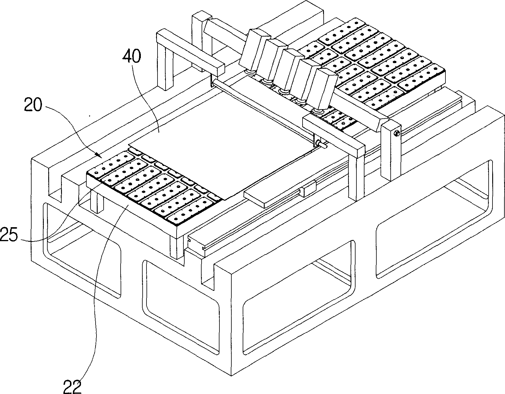
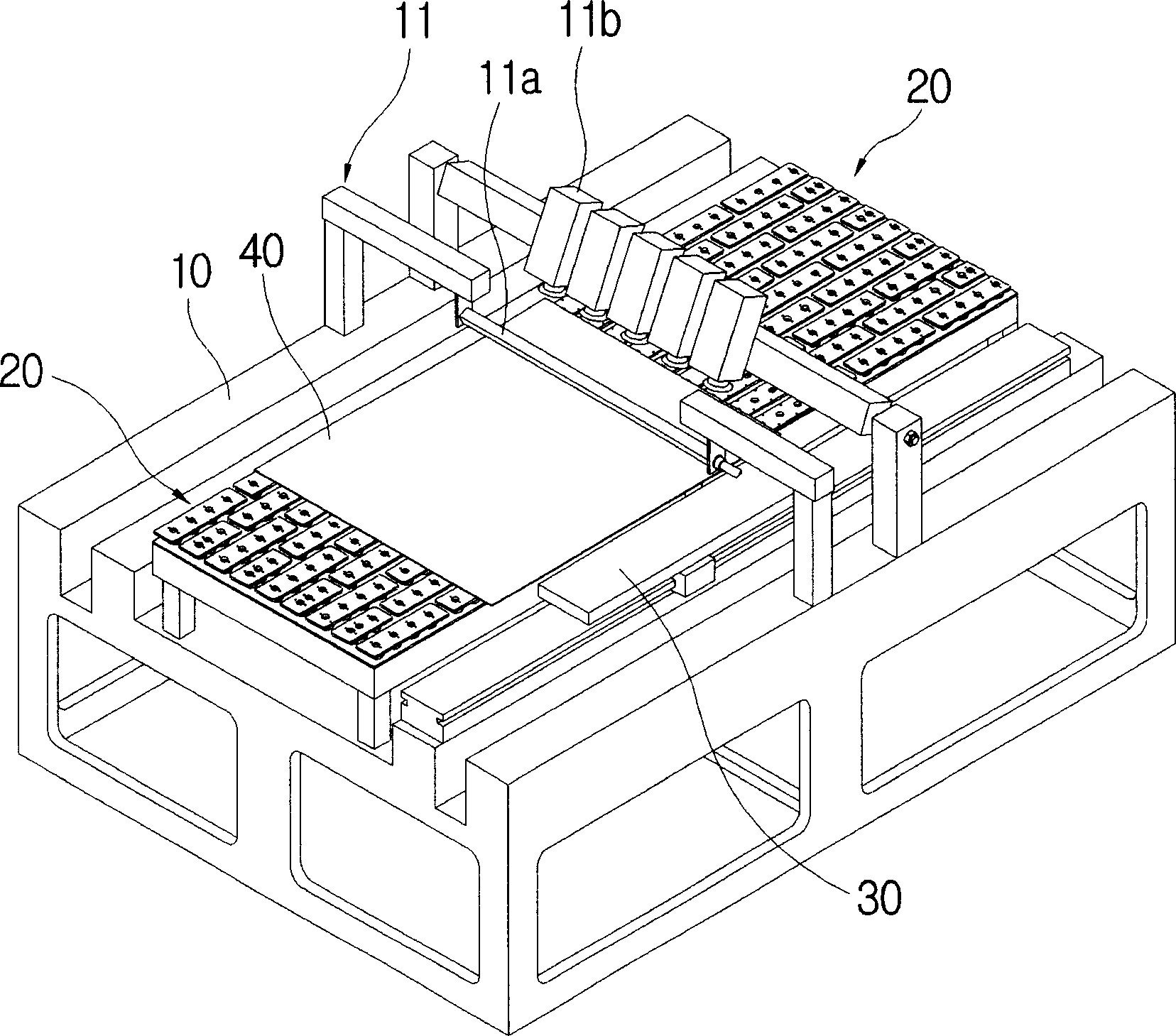
[0033] Such as Figure 3 to Figure 5 As shown, the flat glass conveying device of the present invention includes: a workbench 10 with an inspection part 11 arranged at the center of the upper part; conveying parts that are arranged on all positions of the above-mentioned workbench 10 from the front to the rear and are symmetrical to each other 20 . The conveyor 30 provided above the table 10 adjacent to one side of the above-mentioned conveying unit 20 .

[0034] The workbench 10 is in the shape of a bench-shaped square table, and above the upper surface of the workbench 10 at a certain height, an inspection unit 11 with a light source 11a and an imaging device 11b straddling the workbench is provided.

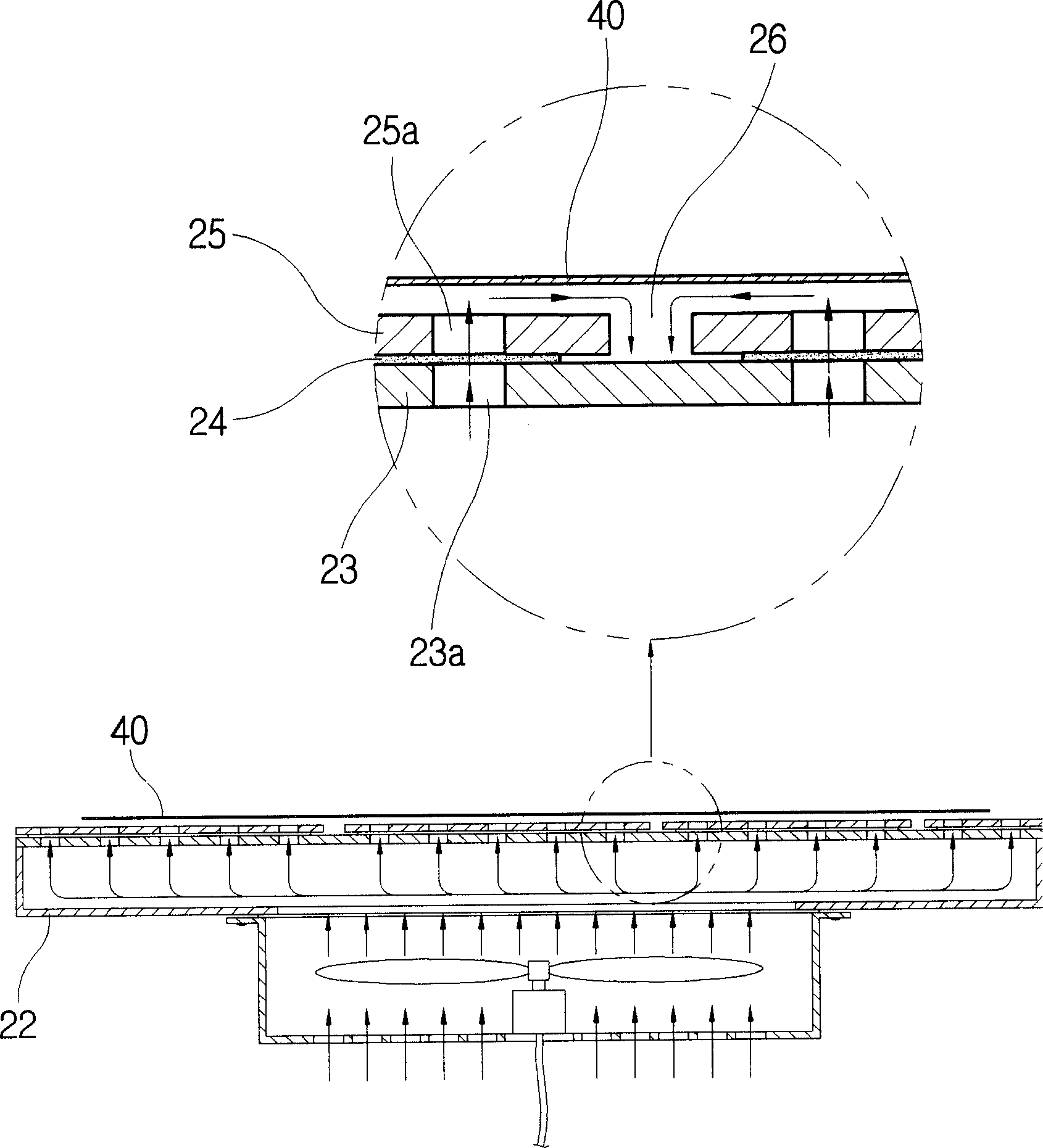
[0035] The above-mentioned transfer unit 20 is provided at a certain distance from the center of the workbench 10 to allow the plate ...


PUM


Abstract

Provided herein is a device for transferring flat panel glass disposed on a panel part of a substrate, in which air was discharged through a mild air layer part underneath the spanel part so as to maintain air layer above the panel part in a stable state. A transferring part was disposed at a working table, a transferring device was set on one side of the transferring part for transferring the flat panel glass disposed above the transferring part. Said transferring part comprises a housing having a fan installed within for discharging air; an air chamber with its top being open and was disposed above the housing; a substrate with a plurality of through holes dispoed on its surface that covered and sealed the opened top of the air chamber. The device for transferring flat panel glass is characterized in that the panel part comprises an inspecting programming pedestal mounted above the though holes of the substrate; a plurality of through holes that connected with the through holes of the substrate were disposed at the center of the panel part; pedestal having penetrating hole for connecting the though hole of the substrate; an inspecting program disposed within the through holes of the inspecting programming pedestal; a plurality of panel partsthat covered the upper part of the inspecting programming pedestal and having a plurality of discharging holes corresponded to the through holes of the inspecting programming pedestal, each of the panel parts was separated by a predetermined distance.

Description

technical field [0001] The present invention relates to a plate glass conveying device, in particular to a plate glass conveying device which smoothly discharges air through an air layer relieving part at the lower part of the plate to keep the air layer on the plate uniform. Background technique [0002] Generally, in quality inspection devices for inspecting thin plate glass for liquid crystal displays (LCDs) and plasma displays (PDPs), as a conveying device for conveying the plate glass to the inspection section side, the following conveying device is used: A plurality of free rollers for supporting and conveying the bottom surface of the flat glass are arranged coaxially on the upper part, and the rotating shafts are integrally arranged along the length direction of the conveying device. [0003] However, the flat glass conveying device using the above-mentioned free roller basically conveys the flat glass in a state where the flat glass and the outer surface of the free...

Claims


Application Information

Patent Timeline
IPC IPC(8): C03B35/14C03B35/24
CPCB65G49/061B65G49/067B65G49/068B65G49/069B65G2203/0208B65G2207/40B65G2249/02C03B35/005G02F1/1303
Inventor 郑孝才李沃基
Owner TAE SUNG ENG
Why Eureka
Try Eureka